on idle (heaters on for all tubes and idle conditions for both channels) I am looking at over 700w of power use. This requires careful planning. The DHT filaments alone require, upon cold startup more than 6 times the current for ordinary operation. Just to give you all an idea a 1000w PC PSU needs the heaters to be preheated by the 5v lines before 12v can be applied, else it goes into protection and I have 40A on a single 12v line.
hey-Hey!!!,
Consider a few volts on g3 to square up the low plate voltage side of the /QUOTE]
I was just discussing that with lem8r the other night. He has no experience with suppressor voltage but this could be a good thing to try out.
I also thought of using g3 as a grid based feedback but smoking-amp showed this could lead to distortion. Will try it out anyway.
Alex,
I am not trying to be harsh either.
However, it's unclear why you even want or need an amp with such a large tube and power output?
If you are planning on making a commercial product, that's one thing.
It's another if it is a hobby project.
Getting a working driver circuit does not require the output stage or the higher B+ for testing, at least I would think so...
As far as getting the parts together, if you don't have the parts on hand, then yes it will have some cost. But the cost of the driver tubes is not high enough to be significant.
As far as the output xfmrs go, I'd say that is the most difficult part of the project by far. Breakdown voltage is a concern, and when you design for high breakdown voltage you may find that it effects some other parameters that are important to bandwidth in the design of the transformer.
Back up. You can take ANY power amplifier and use THAT to drive the grids of your output stage for testing. So, what needs to be built and designed first? Sounds to me like it is the output stage and its power supply. So, the power supply is "standard" since HV power supplies are a known thing, many RF transmitters us tham, and have done so for decades. What is left to work on then?
Spend ur Euros on the output iron, and the chassis for that (whatever you use, could be a thrown out microwave oven? Toaster oven? Blow some holes in it. And see if you can make it work or not... I think you will find the output iron will be very very difficult to make with reasonable bandwidth at that power level.
Define your operating parameters carefully, max output power is likely to not be the ideal operating point... then see what the transformer design looks like. The rest of it comes much later. Otherwise you will dump a ton of money on a very big bass and midrange amplifier...
Just how it seems reading it from afar...
_-_-bear
PS. you'd be surprised at what some people on this list have "on-hand".
well unless I power the DHT at less than nominal voltage I still get:
12.6@44 A (fixed)
+
[whatever the driver tubes require for heating]
+
losses along the line to generate all necessary voltages.
Also bear in mind I need transistor banks to deal with voltage control, linear regulation IC based alone cannot deal with one tube let alone 2 per channel.
If there is an easier way please let me know!
well unless I power the DHT at less than nominal voltage I still get:
12.6@44 A (fixed)
+
[whatever the driver tubes require for heating]
+
losses along the line to generate all necessary voltages.
Also bear in mind I need transistor banks to deal with voltage control, linear regulation IC based alone cannot deal with one tube let alone 2 per channel.
If there is an easier way please let me know!
Each heater gest its own AC trans. A pot across each filament will take care of the rest. I have 813 rigged this way, and 10VAC isn't very much less than 12.6. No issues yet with just throwing the switch...however if your Faith calls for softer start, get a 14V trans and add resistance to the primary; it will come on quite slowly enough. No hum either...
From a 600V g2 supply, try a pair of resistive load 7591. LTP circuit with a CCS. Drop g2 through a resistor( to a common g2 connection ) well below the plate( say 100V ) and run the plates around 300V. Drive it SE or balanced.
cheers,
Douglas
There are quite some designs available:
1600W - Class AB with 2 x GU48
OPT's weight: 25 kg. Pics included
Class AB with 2 x GU81
Class AB2 with 2 x 833
Class A2 with GU81
Why do you need linear reg. for the heaters ? There lots of companies who will build you a customs SMPS for that purpose with current controlled turn on etc. I wouldn't waste my time with a modified ATX-PSU. Not at 44A current. Linear reg. will cause even more heat and that's what you want less wich such an amplifier.
1600W - Class AB with 2 x GU48
OPT's weight: 25 kg. Pics included
Class AB with 2 x GU81
Class AB2 with 2 x 833
Class A2 with GU81
Also bear in mind I need transistor banks to deal with voltage control, linear regulation IC based alone cannot deal with one tube let alone 2 per channel.
If there is an easier way please let me know!
Why do you need linear reg. for the heaters ? There lots of companies who will build you a customs SMPS for that purpose with current controlled turn on etc. I wouldn't waste my time with a modified ATX-PSU. Not at 44A current. Linear reg. will cause even more heat and that's what you want less wich such an amplifier.
@the_manta SMPS for filament supply with current control? COuld you send me a link? I am very interested. is there any high frequency noise to be heard? Are such SMPS designed for DHT?
@ Bear ...I am a proud owner of a huge mercury rectifier (40cm in height) but unfortunately it just doesn't help right now
You are right...a driver can be designed and tested. Infact I will do this as soon as possibile. I am waiting for some HV variable board PCBs. Should give me the freedom to experiment at various voltages.
RF power sections are hard to come by at a reasonable price in Italy. I must take out an edcor spare piece and build a multiplier bank. Reasonable enough. WIll get on that as soon as possible.
output transformers will be required for PP testing at one point or another. The rest I have or am in the process of acquairing (negotiating for a large stock of PO caps ecc at this very moment).
I will take lem8r design and try it out.
The computer ATX was just an experiment...instant current draw is quite demanding.
One tradeoff with transmitting tubes is often due to the relatively high plate circuit impedance, requiring high voltage and a high impedance OPT to reach the highest output power levels. The GU81 is not too bad, able to sink over 1 amp and swing down close to 100V, so your OPT can be of reasonable primary impedance and you can operate at lower voltages efficiently.
The OPT will likely present some conflicting design optimizations but maybe something in the 5K or less plate-plate (1250 ohms plate load in class B) can be done at the >500W power level. I have a pair of 300W OPTs that are 8K plate-plate...
With local feedback only, you're limited to effective plate resistance of >= 1/gm or about 200 ohms in your case plus the OPT DC winding resistance. That makes the 5K plate-plate sort of a minimum Zpri to have a decent output damping factor.
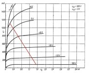
Do you have a load line? A pair of these could produce up to about 1300 watts output in class B or AB2 at 2KV or greater anode supply. There is however a really nice load line at 1500V and 1250 ohms (5K plate-plate) that would yield 600-750W output power. Drive voltage would need to be about 200V peak each tube (400V p-p per side)
If you do use local feedback, you could use a pentode like the 6V6 for the driver, feedback to the driver plate before the MOSFET follower. The MOSFET follower needs to be biased with enough current to reliably pull down the grid of the GU-81.
AC will be fine for the filaments as someone else suggested, with a separate cheap transformer for each tube using the filament center tap cathode connection.
1500V is easily obtainable by using a voltage doubler with a 600V ICT wired backward. A 2KVA unit could just about power one channel.
The OPT will likely present some conflicting design optimizations but maybe something in the 5K or less plate-plate (1250 ohms plate load in class B) can be done at the >500W power level. I have a pair of 300W OPTs that are 8K plate-plate...
With local feedback only, you're limited to effective plate resistance of >= 1/gm or about 200 ohms in your case plus the OPT DC winding resistance. That makes the 5K plate-plate sort of a minimum Zpri to have a decent output damping factor.
Do you have a load line? A pair of these could produce up to about 1300 watts output in class B or AB2 at 2KV or greater anode supply. There is however a really nice load line at 1500V and 1250 ohms (5K plate-plate) that would yield 600-750W output power. Drive voltage would need to be about 200V peak each tube (400V p-p per side)
If you do use local feedback, you could use a pentode like the 6V6 for the driver, feedback to the driver plate before the MOSFET follower. The MOSFET follower needs to be biased with enough current to reliably pull down the grid of the GU-81.
AC will be fine for the filaments as someone else suggested, with a separate cheap transformer for each tube using the filament center tap cathode connection.
1500V is easily obtainable by using a voltage doubler with a 600V ICT wired backward. A 2KVA unit could just about power one channel.
Attachments
Each heater gest its own AC trans. A pot across each filament will take care of the rest. I have 813 rigged this way, and 10VAC isn't very much less than 12.6. No issues yet with just throwing the switch...however if your Faith calls for softer start, get a 14V trans and add resistance to the primary; it will come on quite slowly enough. No hum either...
From a 600V g2 supply, try a pair of resistive load 7591. LTP circuit with a CCS. Drop g2 through a resistor( to a common g2 connection ) well below the plate( say 100V ) and run the plates around 300V. Drive it SE or balanced.
cheers,
Douglas
OK for AC (didn't liek the idea at first) but I do have a CT so I guess that rules out the pot (shouldn't be necessary anyway)
One tradeoff with transmitting tubes is often due to the relatively high plate circuit impedance, requiring high voltage and a high impedance OPT to reach the highest output power levels. The GU81 is not too bad, able to sink over 1 amp and swing down close to 100V, so your OPT can be of reasonable primary impedance and you can operate at lower voltages efficiently.
The OPT will likely present some conflicting design optimizations but maybe something in the 5K or less plate-plate (1250 ohms plate load in class B) can be done at the >500W power level. I have a pair of 300W OPTs that are 8K plate-plate...
With local feedback only, you're limited to effective plate resistance of >= 1/gm or about 200 ohms in your case plus the OPT DC winding resistance. That makes the 5K plate-plate sort of a minimum Zpri to have a decent output damping factor.
Do you have a load line? A pair of these could produce up to about 1300 watts output in class B or AB2 at 2KV or greater anode supply. There is however a really nice load line at 1500V and 1250 ohms (5K plate-plate) that would yield 600-750W output power. Drive voltage would need to be about 200V peak each tube (400V p-p per side)
If you do use local feedback, you could use a pentode like the 6V6 for the driver, feedback to the driver plate before the MOSFET follower. The MOSFET follower needs to be biased with enough current to reliably pull down the grid of the GU-81.
AC will be fine for the filaments as someone else suggested, with a separate cheap transformer for each tube using the filament center tap cathode connection.
1500V is easily obtainable by using a voltage doubler with a 600V ICT wired backward. A 2KVA unit could just about power one channel.
Great advice. Thanks!
Scary project!
You could also warm up with a slightly more modest tube, the GU-46. Needs only 8.3V/15A per tube to heat up. You can run it in A1 with 600V on plate and screen at 500mA.
More modest? Surely you're joking...that is a 500W Tantalum plate. It does look like a 3-grid pentode, and I'd have to put it in the same class as the GU81m.
cheers,
Douglas
Yes, I was only joking. The two pentodes are quite similar, but gu81m's filament is a bit easier to deal with, 12V filament with center tap, so maybe AC is just fine; then grid 3 is on top, whereas grid 3 on the gu46 is part of its base, so it's more difficult to connect to it.
But both of them have low plate resistance: Rp of gu81m at 2kV Rp is similar to Rp of gu46 at 1kV, if I'm not mistaken.
But both of them have low plate resistance: Rp of gu81m at 2kV Rp is similar to Rp of gu46 at 1kV, if I'm not mistaken.

HI all, just a question.
As part of the learning experience I am trying to use my gas rectifiers (either for b+ or less likely for screen voltage).
I was thinking of a full wave setup CLC with small enough input capacitor so as to not cause the rectifiers to arc. DUncan's PSUDII is currently the software I use.
The basic schematic which shows my idea for a power supply is attached to this post.
I just have a couple of questions.
1) to reduce hum I wanted to use the filament transformer CT as my source of B+. Often one cathode terminal is used but some research and reading almost conclusively showed that better regulation and noise rejection is achieved by using the CT.
2) The transformer needs to be customed made since the rectifiers are huge. The current demand for basic functioning is close to 45A for both tubes @5v CT.
Since this xformerneeds to be customed made I would like to ask some questions:
a. given voltage in the filament xformer's windings it will have to have the same 3kv isolation as the main High voltage transformer. Are other considerations necessary?
b. B+ will ikely be 1600v +/- ripple and current will (in the worst of circumstances) not exceed 1.5A. Is adequate voltage isolation and current headroom all that is necessary to build the transformer?
Sorry for the dumb questions but these rectifiers and the B+ envolved are somewhat unusual!
Thanks
Alex
Attachments
I must be a noob because I really did not get the reference to "your mileage may vary"
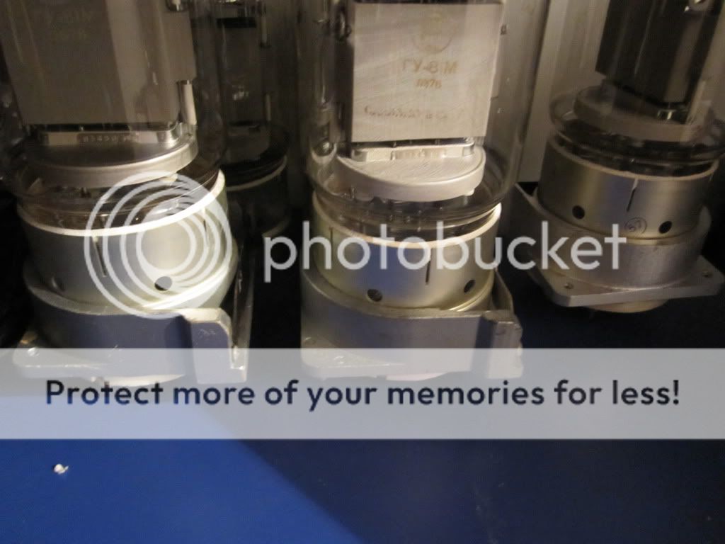
Mercury rectifiers are not practical but I do have large rectifiers which are just sitting in a large frame in my cellar/basement. Large units, plenty of headroom for current and voltage should provide a reasonably decent B+ supply.
From my research I found out that B+ is less important than a good screen voltage b+.
I have spare high voltage caps, decent chokes can be found and these mercury rectifiers are undoubtedly nice to look at.
The problem til now was getting my hands on a decent filament trasformer which could provide the current and isolation ratings needed for the high B+. I should have solved this problem so why not use them?
I promise to go SS for screen voltage
According to lem8r the filament transformer is just a conduit for unfiltered B+ and should only be constructed to sustain the additional current and voltage. I have found nothing on the net or in books to actually disprove this belief. Also large transformers originally built for tube rectifiers do not show significant variations from what would appear to be a normal, high current, low voltage transformer. I guess there are no requirements for, say, larger core o anything of the sort.
Sorry for the delay in updating the topic.. quite a lot of progress has been made. A lot of material is available to me right now so I can start assembly of the final chassis. Sorry but not all the material is depicted in the photos (will update soon) but onyl chassis and transformers (custom made)
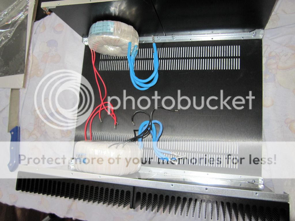
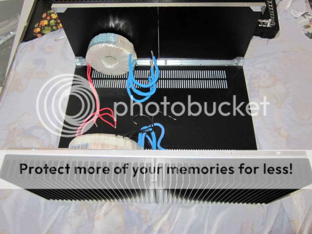
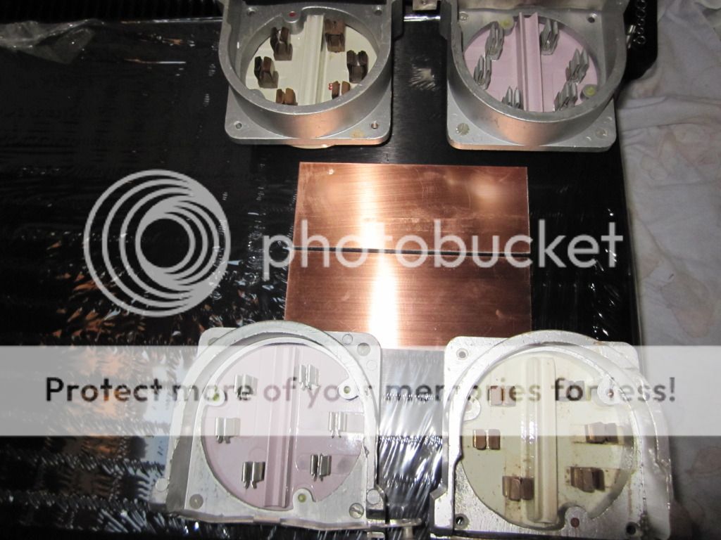
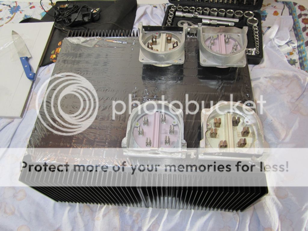
- Status
- This old topic is closed. If you want to reopen this topic, contact a moderator using the "Report Post" button.
- Home
- Amplifiers
- Tubes / Valves
- High voltage driver for AB2 operation GU81m tubes