I would suggest you read the next sentence:
"Yet another cause of transformer saturation is the presence of DC current in the primary winding. Any amount of DC voltage dropped across the primary winding of a transformer will cause additional magnetic flux in the core."
Yes Ohm's Law applies - the DC voltage (small) dropped across the DCR of the primary winding (for a long time) is what cause the magnetic flux to increase.
Dave you are really a tough one!
It once more proves that you still don't understand Ohm's Law....
One more try:
The primary winding of a transformer has a DC resistance, right? Let's say 10 ohms.
What happens when connecting a DC voltage source, let's say 20 VDC at one end?
By now you mastered Ohm's Law, Dave
") rolleyes, so yes, 2 A of DC current through the primary!
rolleyes, so yes, 2 A of DC current through the primary!In other words (exactly like the quote of your link): "Any amount of DC voltage across the primary winding of a transformer will cause additional flux in the core" because DC voltage across the primary means DC CURRENT.
It's about time that you admit your ignorance
Yes at DC but not for AC.
My understanding is....
It is quite possible to saturate the core of a transformer by applying too many AC volts to the primary even without pulling any current from the secondary. The other way to do it is to use a lower fequency e.g use a 60Hz transformer at 50Hz. This is nothing to do with current, it results from the applied volt-seconds!
As long as you don't saturate the core by the above means or some dc it is not possible to saturate the core by pulling too much current out of the secondary. In reality the voltage sags under current and the flux density is therefore reduced.
Maybe I'm wrong and MJ is correct when he states that the large charging currents caused by ss recifiers charging large caps can cause transformer saturation. If I am wrong I would like to understand why.
Yes I was just thinking that myself "maybe the charging is asymmetic".
Looks quite symmetrical here though:
http://www.amazon.co.uk/Building-Va...=UTF8&qid=1325876611&sr=8-5#reader_0750656956
see preview of page 7.
Looks quite symmetrical here though:
http://www.amazon.co.uk/Building-Va...=UTF8&qid=1325876611&sr=8-5#reader_0750656956
see preview of page 7.
Last edited:
EACH charging pulse is obviously (uni)directional, and the very next one is equal and opposite. Assuming a full wave rectifier.
Wow, I discovered AC is really multi-DC. Do I win a prize?
Depends on the load current (assuming some class B) so it's the wooden spoon I'm afraid
Yes and MJ states that the nosiy leakage flux results from the saturation of the core (which results from too much peak current).
Yes, each half of the core saturates in turn from the charging pulses. That leakage flux waveform is precisely what you'd expect.
Diode switching noise pulses look entirely different.
Chokes and power trafos are SET OT's alike.
Expand please.... gap and no gap ? the BH and hysteresis loop transversal curves are quite different between the two...Maybe I didn't follow you.
richy
Diode switching noise pulses look entirely different.
Yes, having thought a bit more, you are right.
Back on topic - any comments on post #14?
When I remember well the LF instability issue with the Williamson amplifier has more to do with tuning of the multiple time constants of the RC couplings.
It is not typical for a Williamson type but for every multiple RC coupled amplifier applying GNF.
Nonetheless the quality of the OPT should not be a limiting factor.
Expand please.... gap and no gap ? the BH and hysteresis loop transversal curves are quite different between the two...Maybe I didn't follow you.
richy
PLS let's not go too far into the matter.
It was a general answer to a particular question regarding core saturation just to have an idea in respect of DC.
Overall core material has limited volume and therefore contains limited number of electrons that could provide limited additional electromagnetic field in response to outer one which means any real core could be saturated either by DC or AC gaped or no.
Otherwise we can end up with Planckion particles
Last edited:
dgta.....Quite correct. With my amp design approach, aka Williamson, I've been able to get a regular stability margin at both audio band extremities of +15dB on top of the nominal 20dB global nfb before instability commences with most makes of o/p transformers. For a given o/p transformer b/w, the rest is down to optimising 1st stage zobel and selecting the global feedback step response with squarewave assist. That's where the experience is required.
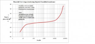
Stability issues is also mentioned in MJ 4th ed book page 469 which I'm nit-picking through scribbling remarks. The phaseshift response of my 200W design is in pic.
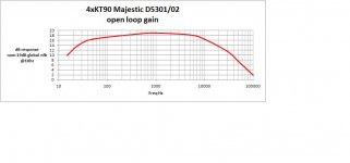
I calculated that optimising the L freq end transient response coincides with the transformer iron f2 distortion being around 1.4% at the f3 cutoff design frequency. There is nothing wrong with this value sonically, possibly sounding more open bass with large cabinets, but a circuit having a large enough amount of iron will reduce the distortion, enable a lower response and permit adequate LS damping by enough reserve closed loop gain. This is a standard requirement in all amps. A loop gain plot from the 200W Williamson version is shown. O/P transformer f3 is 15Hz. (a large transformer)
Choosing the correct coupling caps and grid leak resistors from the concertina to the diff driver will enable an optimum LF transient response, a long way before instability occurs.
The mistake in many original designs was far too high values of interstage coupling caps used as described in MJ Valve amps 3rd ed page 414 (4th ed page 470-2), encouraging extended loop gain well below the o/p tranny cutoff. This is never required and asking for trouble on a Bode plot;- an example of the overhang effect is listen to music with a fairly large proportion of Minimoog synthesiser, gated with an LF warble with a lower tone, and directed into an over-compensated Williamson design with the volume really wound up; and it sounds awful, as the excessive RC circuit time constants makes the global nfb loop struggle to correct the long circuit response between transients. Or in other words, an effect of amplitude modulation created by a long subsonic timeconstant which is a considerable portion of the signal. Suprisingly, the vinyl version copes very well.
Herb Alpert ; the number, "Latin Lady" is a good example. Mixed digital and analogue make interesting listening comparisons. One must remember the Williamson design was fine for standard reproduction with the type of music in it's day that had relatively slow rise times, but modern day music with faster attacks does create sonic issues when excess LF slewing and blocking occurs.
BIG never ending subject. My dual 200W Williamson design makes a good comparison..with optimised feedback loops, transient response and very low distortion; currently under bench test.
Keep listening.
richy
Stability issues is also mentioned in MJ 4th ed book page 469 which I'm nit-picking through scribbling remarks. The phaseshift response of my 200W design is in pic.
I calculated that optimising the L freq end transient response coincides with the transformer iron f2 distortion being around 1.4% at the f3 cutoff design frequency. There is nothing wrong with this value sonically, possibly sounding more open bass with large cabinets, but a circuit having a large enough amount of iron will reduce the distortion, enable a lower response and permit adequate LS damping by enough reserve closed loop gain. This is a standard requirement in all amps. A loop gain plot from the 200W Williamson version is shown. O/P transformer f3 is 15Hz. (a large transformer)
Choosing the correct coupling caps and grid leak resistors from the concertina to the diff driver will enable an optimum LF transient response, a long way before instability occurs.
The mistake in many original designs was far too high values of interstage coupling caps used as described in MJ Valve amps 3rd ed page 414 (4th ed page 470-2), encouraging extended loop gain well below the o/p tranny cutoff. This is never required and asking for trouble on a Bode plot;- an example of the overhang effect is listen to music with a fairly large proportion of Minimoog synthesiser, gated with an LF warble with a lower tone, and directed into an over-compensated Williamson design with the volume really wound up; and it sounds awful, as the excessive RC circuit time constants makes the global nfb loop struggle to correct the long circuit response between transients. Or in other words, an effect of amplitude modulation created by a long subsonic timeconstant which is a considerable portion of the signal. Suprisingly, the vinyl version copes very well.
Herb Alpert ; the number, "Latin Lady" is a good example. Mixed digital and analogue make interesting listening comparisons. One must remember the Williamson design was fine for standard reproduction with the type of music in it's day that had relatively slow rise times, but modern day music with faster attacks does create sonic issues when excess LF slewing and blocking occurs.
BIG never ending subject. My dual 200W Williamson design makes a good comparison..with optimised feedback loops, transient response and very low distortion; currently under bench test.
Keep listening.
richy
Attachments
Richy,
IMO, the place to bandwidth limit an amp with NFB is at its I/P. A high pass pole in the 15 to 17 Hz. range gets the job done. Once you've disposed of any infrasonic crud at the I/P, interstage coupling caps. placing the high pass poles inside the NFB loop below 5 Hz., which is good for LF stability, doesn't expose you to O/P trafo core saturation.
BTW, SY has stated that using a different F3 in the high pass poles between the "concertina" phase splitter/differential amp and differential amp/"finals" is important for stability in Williamson implementations. I totally agree. Practical considerations cause a builder to make the splitter/differential amp pole closer to 0 Hz. than the differential amp/"finals" pole.
SY has stated that using a different F3 in the high pass poles between the "concertina" phase splitter/differential amp and differential amp/"finals" is important for stability in Williamson implementations.
Yes, one would think that's pretty obvious and also easy to do. Since the grid resistor typically has to be much smaller on the finals, usually by a ratio of 1:3 to 1:5, you can use the same exact capacitors and have the time constants well apart.
Richy,
IMO, the place to bandwidth limit an amp with NFB is at its I/P. A high pass pole in the 15 to 17 Hz. range gets the job done. Once you've disposed of any infrasonic crud at the I/P, interstage coupling caps. placing the high pass poles inside the NFB loop below 5 Hz., which is good for LF stability, doesn't expose you to O/P trafo core saturation.
BTW, SY has stated that using a different F3 in the high pass poles between the "concertina" phase splitter/differential amp and differential amp/"finals" is important for stability in Williamson implementations. I totally agree. Practical considerations cause a builder to make the splitter/differential amp pole closer to 0 Hz. than the differential amp/"finals" pole.
Correct.......so an output tranny using an E&I core is actually a better choice for an amp with global nfb loop as the miniscule airgaps of the E&I laminations (lower permeability acting as a node pole) assists to curtailing the global nfb Loop Q at very low frequencies without the permeability dropping due to misbalanced core BH. This bonus allows for a 5-10% automatic allowance for an DC out of balance output stage without medling with the currents. Implying don't swap o/p transformers to a toroid without doing the circuit math ! The fantastic permeability of a "closed core" C or toroid can be a recipe for creating an amp into a perfect LF oscillator. So as Eli mentions; the f3 amp interstage coupling timeconstants in the amp has to be backed off. Not increased as per Williamson & Keroes article.
Another check for those curious is to run an amp with LF oscillator into a dummy load till near clipping, note the level. Drop the frequency and reduce subequent input level to avoid output tranny saturation and again note levels. Don't use ones best tubes for this ! as most amps object to this kind of output stage hammering. One will be suprised how little level it takes at the subsonic LF end to upset a well designed power amp.
This subject is never ending; the amount of closed loop gain and negative feedback all pile in, at the end of the day I have some remorse in designing with less global nfb than is required, it can sound "less tight" or whatever, but those who are against global nfb, think again, as on an AC cycle to cycle basis (akin to a current mode switchmode power topology) global nfb does correct the mismatched AC tube gm on a cycle per cycle basis. TRy it by plugging a mismatched o/p tube of the same make and observe thd and one can then say global nfb does a pretty good job.
Wild cases in MI, I've done it, a 6550 and a 6L6 in opposite sockets is forcing the issue where the loop cannot compensate for a 2:1 variation of gm. Sounds good and raucous.
Good intituative subject for those who can follow it.
I aslo have another dual 200W with 15Hz HP 18db/oct input filter...doing comparative tests.
richy
- Status
- This old topic is closed. If you want to reopen this topic, contact a moderator using the "Report Post" button.
- Home
- Amplifiers
- Tubes / Valves
- Which KT88 PP and which Transformers?