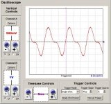
I recently (re)built one of my amps and I've come across a small problem. When I initially listened to the amp, it sounded like crap; loads of distortion. Upon scoping it, there was a large amount of crossover distortion.
The design and schematics can be seen here: audio diy
The circuit was built exactly as seen in the schematic with the exception of the 270r cathode resistor and the inclusion of CRC filter in the power supply. The cathode resistor was replaced with a simple LM317 CCS.
The test signal is a 70hz sine wave 350mv P-P. I'm not sure of the exact quiescent current but the voltage from cathode to ground is approx 28v.
Does anyone have any ideas where/what the problem might be?
Attachments
the cathode is not low enough impedance. divide the push pull cathode and use 2 ccs (one per cathode circuit) or use the resistor-grouped cathode method like you had originally.
I don't like using ccs in the final stage since it effects the dynamic headroom of the output stage.
I don't like using ccs in the final stage since it effects the dynamic headroom of the output stage.
the cathode is not low enough impedance. divide the push pull cathode and use 2 ccs (one per cathode circuit) or use the resistor-grouped cathode method like you had originally.
I don't like using ccs in the final stage since it effects the dynamic headroom of the output stage.
The 832A is a dual beam tetrode with a common cathode within one envelope. There is no way to separate the cathodes.
You need a way of adjusting the cathode current to get rid of cross over distortion.
I am using a small trimpot with the LM317 CCS. Increasing and reducing current has no real affect on distortion.
Is it possible that the distortion is coming from the driver stage? I haven't had time to scope this section yet.
In the picture of your first post, there is no cross over distortion, which should appear symmetrically at rising and declinig side of the half cycle.
Instead this is unsymmetrical and possibly caused by saturation of the OPT's core.
At input ? What is output level ?
Take that time. With a scope you will see immediately where the problem comes from.
Instead this is unsymmetrical and possibly caused by saturation of the OPT's core.
The test signal is a 70hz sine wave 350mv P-P.
At input ? What is output level ?
I haven't had time to scope this section yet.
Take that time. With a scope you will see immediately where the problem comes from.
the only way I see is to get the impedance down in the cathode (if it was ok, then substituting the ccs caused the xover distortion).
use a mosfet based ccs instead of a bjt based like the lm317 voltage reg.
otherwise, I would directly ground the cathodes and run grid bias, but I'm kinda of a brute force guy.
grid leak resistor method- tieing the grid resistor 390k to the top of the ccs-cathode might give you that extra bit of electrons from grid leakage, but the mosfet based would be more of an academically sound choice.
Last edited:
What kind of scope are You using?
Also, where are You checking the output signal?
Is the problem happening on both channels?
As a general troubleshooting steps, I would:
- Replace the output tube just in case.
- Check the components for wrong values or connections, restoring the original cathode resistor and cap to start with.
- Then check all the the voltage points.
- Then disconnect the feedback loop for a while to make further tests.
- Use a sine wave and a square ware at 1Khz (one at a time), 100mV at the input, so one can compare the results.
- Then use a scope to read the signals at anode of the amplifier section 12AT7 to see how clean is the signal.
- Then look for the signals at the inverter outputs (anode and cathode) of the second section of the 12AT7and compare them; it should be of the same amplitude but in opposite phase.
Good luck!
In the picture of your first post, there is no cross over distortion
Exactly; this is not cross-over distortion.
What OP-transformer are you using?
A simple way to check if the CCS is to blame is of course to just replace it with the original cathode RC-complex.
With the cathode at 28V at present it seems to me that you're running the tube with too high bias getting into the non-linear region; check curves. It won't cause the distortion you're experiencing but it also won't sound very good. Probably somewhere around 20-25V is suitable, but don't go above 25V.
Pushing this tube into AB2-operation with a fixed-bias, grounded cathode and a suitable CF/CCS-drive seems more rewarding, judging from the curves. You're getting (should be getting) around 7-8 Watts from your design, but this tube holds potential for a lot more imho.
rgds,
/tri-comp
Last edited:
I agree with Artsolo, that is not x-over dist. The first thing I would do is check the testsignal at input tube, then grids of the 832. If all is well there, I'd disconnect the feedback, then send in a testsignal 500-1kHz, 100mV like Jebem said, and go from there.
At 70Hz the output transformer may be either giving you a phase shift (which may explain the non-symmetric waveform) or even be saturating (not likely), so using a testsignal that rules out the transformer is a better idea. Once you've figured out the amp at midfrequency, you can check out the low- and high extremes.
At 70Hz the output transformer may be either giving you a phase shift (which may explain the non-symmetric waveform) or even be saturating (not likely), so using a testsignal that rules out the transformer is a better idea. Once you've figured out the amp at midfrequency, you can check out the low- and high extremes.
A CCS in this circuit maintains a constant mean current. What you actually need is a constant quiescent current. Not the same thing at all. You either need to run the valves hot with no signal, or accept crossover distortion with large signal as the bias shifts due to second-order distortion. Simple cathode resistor bias is better than CCS bias, as it partly compensates for bias shift with signal. Best of all is voltage bias.
Hm. The scope traces look like possibly an issue with the driver tube. You might try increasing the value of the grid stop resistor significantly (100K) and see if some of the problem sorts out. I could be off on a different planet but the distortion looks more complex than just a simple output tube bias issue.
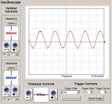
Today, I have replaced the CCS with the cathode resistor; there is approximately 21.5v across it. I forgot to mention that I didn't use any feedback; I typically don't use any NFB unless it's really required. I also swapped out the OPT for another unit(same specs).
The amp sounds much better(little bit less distortion) than yesterday but still seems to distort at lower frequencies.
I've found that one half of the 832A is drawing 29.5mA while the other side is drawing 36mA. I don't think it'll make much of a difference as it's already well biased into AB1. The driver section doesn't seem to amplify the input signal a whole lot; I'm wondering if I'd be better off removing the cathode follower and directly driving the grids(operating in AB2)...
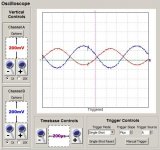
Here are some traces from the driver section and the output from the OPT.
Test signal is 1kHz @ 350mv P-P; It seems that the amp requires alot of drive.
Thanks for all the suggestions!
The amp sounds much better(little bit less distortion) than yesterday but still seems to distort at lower frequencies.
I've found that one half of the 832A is drawing 29.5mA while the other side is drawing 36mA. I don't think it'll make much of a difference as it's already well biased into AB1. The driver section doesn't seem to amplify the input signal a whole lot; I'm wondering if I'd be better off removing the cathode follower and directly driving the grids(operating in AB2)...
Here are some traces from the driver section and the output from the OPT.
Test signal is 1kHz @ 350mv P-P; It seems that the amp requires alot of drive.
Thanks for all the suggestions!
Attachments
Last edited:
I forgot to mention that I didn't use any feedback; I typically don't use any NFB unless it's really required.
Now it is required, really. Your output stage is pentode connected and thus the output impedance is high. This causes high distortion at low frequency. In case of UL or triode the case is essentially better.
Your driver stage seems to be a cathodyne. It's gain should be less than 1.The driver section doesn't seem to amplify the input signal a whole lot
I'm wondering if I'd be better off removing the cathode follower and directly driving the grids(operating in AB2)...
What cathode follower ? I am confused now.
You have an unbalance of 20% DC current between the two sides of the output transformer. Unless you have a BIG iron transformer to deal with this unbalance situation, this amplifier will distort heavily specially at low frequencies.
The anode current of the output tubes should be equal to make sure the output transformer is not saturating with direct DC current.
That is the idea behind push-pull designs, so we need a way to DC balance the output tube stages.
I suggest an additional bias supply to feed the output tubes control grid resistors, using two adjustable resistors.
Sorry, I meant to say cathodyne; got my topologies confused. Would it be better/simpler to directly drive the power tube?
I'm thinking that this will also allow for AB2 operation without any sophisticated driver designs.
Doing a CF AB2 drive doesn't have to be very sophisticated to work really well.
I did this one for my 2C34/RK34 dual-triodes, also with common cathode.
You may drop the CCS and replace it with something like 22K-ohm, reducing the negative supply to probably -50V
It did sound like crap at low frequencies before adding NFB. Absolutely NO control over bass. AFTER the NFB was applied it sounds very firm and in total control.
I did an improved cathodyne with built-in amplification. I'll post the schematic if you're interested.
rgds,
/tri-comp
Attachments
Hi db!,
remember the purpose these tubes are intended for: RF class C PP mode. That means they run more as switches than as amplifiers. Thus for the tube manufacturers there was no use in balancing both systems within the envelope. The results one should expect from this are exactly the same as you described in your posting #12. *imho* these tubes are simply unsuitable to be run as AF PP amplifiers.
Best regards!
You now have 21.5V on the cathode. With the CCS you had 28V, so you were much nearer cutoff - that would rise even further when signal is present. You have significant imbalance too. I think you were seeing crossover distortion, but it was unbalanced by the poor valve matching.
Many of these tetrode RF output valves were characterised for audio too - have a look at the data sheet. I'm not familiar with this particular one. However, it would probably have been PA or AM modulators not hi-fi so a bit of distortion was OK.
Many of these tetrode RF output valves were characterised for audio too - have a look at the data sheet. I'm not familiar with this particular one. However, it would probably have been PA or AM modulators not hi-fi so a bit of distortion was OK.
Hi,
a glance at this thread perhaps might show you the aspect I've meant above. The respective RCA datasheets tell us that the 829B under certain circumstances is suitable for AF amplification, while the 832A isn't.
Best regards!
a glance at this thread perhaps might show you the aspect I've meant above. The respective RCA datasheets tell us that the 829B under certain circumstances is suitable for AF amplification, while the 832A isn't.
Best regards!
There is no good way around the single screen design of the 829B. You could add a negative bias circuit to the grids which would allow you to balance the DC current.
However the tubes would not be balanced ac wise and gm would probably be off between the two sections. Running in class A only would minimize the distortion due to this ac imbalance but will result in lower power out.
Once you go into AB1 operation and tubes alternately shut off, the imbalance will result in increased second harmonic generation.
I would not expect AB2 to improve the situation.
- Status
- This old topic is closed. If you want to reopen this topic, contact a moderator using the "Report Post" button.
- Home
- Amplifiers
- Tubes / Valves
- PP amp crossover distortion