Hey all! Fleshing out a first wave of DIY designs related to microphone preamps, tube summing amps for a recording console, etc... Haven't had much to post, as you all dive deep into esoteric DIY-ing, but mainly use the knowledge base here for troubleshooting stumps...
Here's one that's giving me hell.
I seem to have, if I'm diagnosing correctly, about 1mV of (what looks like) transformer induced voltage on the aluminum anodized chassis I'm building a high gain mic pre on. (The mic pre is dual-pentode; 6SJ7 into EF86 into 6FQ7 CF, unbalanced outs at the moment).
I have observed via o-scope that this ~1mV or less noise signature is on:
- every part of the chassis and every ground in the amp
- the cathodes of the 6sj7 and ef86's
- the heavily filtered B+ line
I wouldn't normally complain about a small dab o' hum at very high gain, but this is a mic pre I'm building for ribbon mics, so it needs to be pretty damn quiet. I'm measuring this noise with the preamp *not* plugged into *anything else*, just terminating the inputs (150R on each leg on primary side of mic xfmr) and outputs (100k to ground after CF output cap). I've measured the same hum/noise levels with the preamp terminated this way, and actually terminated to a mic and mixer. This hum is not in relation to any other interconnected equipment, but is rather being self-induced somehow.
Here's my troubleshooting so far:
- Made sure anodizing is scraped off, making good contact around the chassis. I'm still suspect that this anodized chassis could be the issue. Read on...
- First, wasn't using a star ground scheme. Went through extensive pains implementing a good star ground. No changes.
- Transformer B+ sec CT and first filter cap grounded together to chassis; other two filter caps along with seperate stage grounds all star grounded to second chassis ground point. I have tried to change this to ground at the same place as the CT/first filter, no change in hum.
- Power transformer mounted on outside of chassis. No change if lams are grounded to chassis or not. Rotating PT makes no difference.
- O-scope plugged into same power strip to observe hum. Also tried different strip.
- Tried different grounding spots on the chassis. Disconnected parts of the chassis to try to reduce hum. No luck.
- Tried different power transformer and different voltages. Lower voltages (hence lower currents) slightly decreased this noise on this ground. This leads me to think of some kind of grounding current issue...
- Tried RC filtering as well as LC filtering. No change. It doesn't look like B+ ripple in the first place, anyways.
- Turning AC power off to power transformer stops the hum.
- With the PT 'on', I put a DPST switch to turn off the AC filament line. VERY slight change in sound of hum, but otherwise, no change.
- Tried using filament CT as well as dual matched 100R for filament ground sense. Nope. Tried humdinger balance pot. Nope.
- Tried various outlets in house. Nope. Tried it at work. No change. Injected noise and level is the same in a variety of houses/places/etc.
- Pulled various tubes, tried various tube types, makes, etc. No changes (other than slight gain differences due to tube strength/make)
- Shielded all AC-coupled cabling to/from stages. Cleaner waveform! No hum change.
- No noise change when (momentarily!) lifting the power ground from chassis.
- Noise reduced when I changed power cord ground to chassis from close to the PT to next to (but not the same connection as) the B+ CT / first filter cap ground point.
At this point, and at the start of it, of course, the design is questioned. I don't have the ability to scan anything, but it's a very simple design, two grounded cathode pentodes into a bootstrapped CF. I can isolate each stage and see the noise amplified in each, not dependent on the others. I feel very confident that the design is not to blame, nor is the layout. This is built on perfboard. The PSU part (diodes, first filter cap, etc) is on the wayy other side of the 2RU chassis as the rest of the stages. Lid on/off the amp doesn't change anything, either.
Since I have tried two different power transformers (and even different power cords!), updated grounding schemes to no difference, etc, my suspect is that either this chassis isn't grounding well (hard to believe - it's aluminum!), or that perhaps there is some kind of PT secondary imbalance that's causing there to be noise on the ground. All other tube equipment, amps, etc that I've built or rebuilt all have very quiet 'looking' ground and operate SILENT. However, this build on this chassis...
Any thoughts? I'll try to get a pic of where the build is at now for any troubleshooting in a few days (after new years). Am I neglecting something, here? My thoughts are that this slight noise on ground is getting into the grids and/or cathodes of each stage and then getting amplified. (The waveform is inverted at the plate in respect to what is observed on ground/cathode).
A basic question, too:
Can signal ground noise be coupled into the cathode of a grounded-cathode gain stage, both bypassed or unbypassed?
And, can signal ground noise creep into the grid via the grid leak resistor (or potentiometer)?
Thanks for any thoughts or insight. The amp sounds AMAZING despite this noise/hum.
Last hint: it looks similar to Fig. 2 here: Earthing (Grounding) Your Hi-Fi - Tricks and Techniques
Yes, I know that's a MAGNETIC induced waveform. Hence my dilemma. I'd say 'similar', as it's not symmetrical, but seems to look close to that 'M' shape, and (if my memory is right) it's happening at 60hz.
Last edited:
I had a similar problem with a mixer with a gain of 200 for microphones.
A couple of millivolts amplified ground noise amplified by 200 is massive !
I tracked it down to resistance in the pcb tracks.
I shorted the pcb ground out with wires and this improved matters a lot.
Not sure if it was just cheap chinese pcb copper but I should really have added a ground plane, will know better next time.
Use a battery powered O-scope")
I doubt that the o-scope is inducing a ground loop. On the contrary, noise is there. O'scope plugged in, on or off, doesn't change any of that. I feel I'm 'looking' with accuracy and not anything else being induced or seen falsely.
I had a similar problem with a mixer with a gain of 200 for microphones.
A couple of millivolts amplified ground noise amplified by 200 is massive !
I tracked it down to resistance in the pcb tracks.
I shorted the pcb ground out with wires and this improved matters a lot.
Not sure if it was just cheap chinese pcb copper but I should really have added a ground plane, will know better next time.
Wide-open gain is about ~12000. 80db. First stage gain is ~120, hum/noise is 20mv. Second gain stage is ~18, isolated by itself, noise is about 3mV. Cathode follower gives just about 1mV of noise, about the same that is already on the ground itself. Compile it all together, I've got about 1V of hum running the preamp full blast. Even then, 20mV of noise is ~-32dbU. This is a lot of noise, even considering the gain.
I'm seeing this noise on the chassis itself, seemingly everywhere, as well as on every point of the star ground. So, I feel it's not an interconnect problem. On distant points of the chassis, however, the ground noise/hum is louder on the o'scope. This noise is also directly on the first filter cap/B+ center tap as previously mentioned, and this amp isn't pulling much current... perhaps 50ma peak on b+.
Last edited:
If you are seeing 1mV of noise everywhere you probe (but not on the signal path, as that has increasing noise levels due to amplification), then I suggest you are indeed 'looking' at noise from a loop that includes your O-scope earthing via mains.
Your original post was a little ambiguous about what 'noise' was being reduced (ie. amplified output noise, or O-scope observed level on say a non-signal path point).
Your original post was a little ambiguous about what 'noise' was being reduced (ie. amplified output noise, or O-scope observed level on say a non-signal path point).
no switching power supply. classic full wave cetner tapped rectified with 4n1007 diodes. i've done both little and lots of filtering with no change. tried .1uf bypass caps on c
the noise, which i'd describe as a hum/buzz (so, 60hz with lots of harmonics), is the *same* throughout the original post, to clarify.
so, the o'scope puzzle, eh? here are my troubleshootings about *that*...
1) doesn't happen with any other electronics on my bench. period. never has. so, if it is something that is just 'seen' with the scope, then something in this chassis itself is causing a ground loop.
2) i've also done scope probes with and without the scope probe 'ground' clip on the chassis. all that does is clear up some 'fuzz' i see on any probed signal. you know, this is just kinda standard scope procedure. but, to note, i've worked the scope with ground clip to chassis (or star ground) to no difference (other than a little clarity on the waveform)
3) the 'look' of the waveform produced by the probe when hovered close to/near the power transformer is very similar to the noise that i'm seeing after amplification. when i'm using a large power transformer, i can clearly see about the same waveform on the chassis being conducted. when using a smaller voltage power transformer, i see a very small but similar waveform ripple on the chassis. my rationale, so far, is that since I'm doing more R-C stages and voltage knockdown with the bigger transformer, more current is being used and such the chassis current is higher.
scope is a tek 465, btw. i've done (and still do) great troubleshooting with that thing.
so, let's say, for argument's sake, that I don't have a scope, or that my thought that I'm seeing a 'noisy' ground is inaccurate.
my b+ is filtered very nicely. 68uf after rectifier, 20H choke + 100uf, 4.7k + 100uf (this feeds the 6fq7 CF's and ef86's), then 2.2k + 220uf (to feed 6sj7 input stages).
i have not tried running DC to filaments. i've relooked and re-twisted/tried new layouts for the AC twisted filament wires. the filaments go to the 6fq7 first, then each ef86, then each 6sj7, one at a time, in parallel, of course. however, i've read and deduced that filament hum would be seen as (mostly) pure 60hz, no? and not quite this mangled hum/buzz i'm experiencing. would anyone suggest i try DC for filaments? it's one of the only things i haven't tried. however, my test i noted to turn off the filament line to the tubes (as b+ is still active) for just a few seconds while the tubes are still conducting yielded no reduction to the hum/noise, so this led me to feel that a filament AC problem is not what's causing this.
thanks for the thought help, everyone, so far. i'd like to solve this and add it to the knowledge database here!
i'll try to get some pics in the next few days. i'm moving cross country on friday...
What waveform do you get with the probe ground and tip both connected to the same point on the amp chassis, and other normally probed spots?
It's always worth having a 6V battery available for troubleshooting and preparing high gain amps. Two quick configurations that can help with a better appreciation are (a) just powering the input tube(s) with 6VDC, but leaving the 6VAC wiring pretty closeby, and (b) powering the whole heater chain with 6VDC, unconnected at the transformer end.
Have you tuned the humdinger pot for min hum? Was it very sensitive to pot wiper position?
We could probably offer better ideas if you would post some photos of the circuit, and a schematic.
Not sure about your scope results but you also say that you can HEAR the hum. So I have to believe that something is getting into the input.
Is this single-ended? How do you have the input's signal and corresponding ground conductors arranged/routed? And how is the grid-input's ground-voltage reference conductor (to star ground) arranged/routed?
The only two common "gotchas" that I can think of, to get hum into the input, are:
1) You could have "enclosed loop area", enclosed by the signal input and signal input ground conductors, and/or the conductor from the input ground voltage reference point to the star ground. Any conductive loop, in the presence of a time-varying magnetic field, will have a time-varying current induced in it (Faraday's Law). If the loop includes your signal input or its ground reference, that's definitely trouble. Your input jacks (both signal and signal ground) must be insulated from the chassis. The signal and signal ground wires must be twisted tightly together, all the way from each jack to the ends of the resistor betwen input and ground (the input ground reference point). If a shield is also used (which must NOT carry the signal ground), in addition to twisted pair, then the shield should only be connected to the chassis, and to nothing on the other end. In an extreme-gain case, I would probably also run/twist {the ground reference conductors that go from the ground ends of the input resistors to the star ground} with their respective "input signal and signal ground" pair, back to the input jack (but not connected there of course), and then take those ground-reference conductors (from the two jacks) and twist them together on their way from between the input jacks to the star ground. That should almost totally eliminate the enclosed loop area from the signal input, signal input ground, and signal reference ground conductors.
Of course, any loop with enclosed geometric area can (and will) be either a receiver or a transmitter or both. So you should also: run right next to each other, and tightly twist (even if shielded) if using wires, ALL "natural pairs" of conductors, including all AC pairs, DC power pairs, input pairs, output pairs, heater pairs, etc etc.
And of course you want to keep as much distance as possible between stuff with large and/or very dynamic currents and stuff with low-level or sensitive signals. And any conductors that must approach each other should do so orthogonally.
Do you get hum when the input jacks are not connected to anything? What about when you short the input jacks, or connect a small resistance across each one? If "no" for first question and "yes" for second question, or if there is a big difference in the hum for those two cases, then the hum is almost certainly due to enclosed loop area of the input signal/ground conductors.
Have you only tested it with the chassis open, and perhaps (but not necessarily) with fluorescent lighting nearby? With that much gain, I'd also try it with everything buttoned-up, to see if there's any change at all. If so, it's probably due to enclosed loop area in your input circuitry.
2) You could have the input ground voltage reference point's return to the star ground sharing some length of conductor with another ground return. Trace and wire resistance isn't the only problem, and may not be the main problem when the currents are time-varying. In addition to the voltages induced across the parasitic resistance, the conductor's parasitic inductance induces a voltage that's proportional to the time-rate-of-change of the current, regardless of the current's amplitude. Any such induced voltages will appear back at the non-ground end of all of the conductors that share any length on the way to the star ground. If one of them attaches to the "ground" end of a resistor that's between an amplification device's input pin and "ground", then those induced voltages will be arithmetically summed with the input signal voltage. And that's trouble.
If you have two probes and can use differential mode (one channel minus the other) you could put one scope probe at the star ground and one at the "ground" end of the resistor from grid to ground (assuming you have something like that in the circuit). Or, if they're close enough to each other, you might get away with attaching the ground wire from a single probe to the star ground, and probing the same input ground reference point. Disclaimer: I guess I can't remember actually trying that. It might not work with standard probe types.
Cheers,
Tom
Last edited:
better yet, put the capacitor between the heater referencing resistors and DC ground. you need only to ac couple the heaters (through a cap) to dc ground. The hum balance range should be infinite now, and it doesn't matter if you reference it to one side of the heaters and without resistors too.
Last edited:
following up to an old post:
sorry, dave - that didn't work.
tom - just finding out how to draw schematics using programs. i'll get to it...
i went through extensive pains for a star ground, but, of course, that's not the issue.
i believe it's this anodized chassis (which is now butchered to shreds). i've had problems with grounding it simply by scratching off the anodized portions where the panel screws mount; even though on a DMM, I get continuity, I believe that not having full connection all around is causing a series of small ground loops throughout the chassis. even though the signal path is star grounded, there is an eddy of ground currents that radiates, in different amounts in different sections, the further away I probe from the AC chassis ground.
that's very interesting to me - how, with a complete signal star ground, and the only other ground point to chassis is the AC ground, there's still loops going down throughout various parts of the chassis...
i'm ordering a non-anodized chassis, will re-build, and see if that fixed it. i need to, anyways, for appearances.
reviving; had to move; life changes; now, back on the bench.
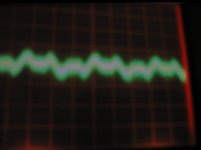
here's a picture of the o'scope looking at the chassis ground of the preamp. so, the ground noise is at about 5mV. this exact same waveform that is on the ground is hence on anything that is referencing to chassis ground.
does that make sense?
i've tried multiple grounding schemes and considerations, which only bring the noise of the preamp down to the noise seen on the ground, as seen here. currently, i have a star ground. the first filter cap and PT center tap are tied together at one chassis point; all other points are star grounded together (each filter stage; each tube stages' cathode; each stages' grid; each stages' vol pot; anything being considered has an individual heavy gauge lead to star ground); further, the mains ground is connected through a short, heavy gauge wire at the mains input. no hum improvement tying the two ground points (PT/first filter and 'the rest) together.
most specifically, this noise is seen on the (grounded) secondary side of the input transformer, so, it's being included with any input signal. ~5mv of noise then hitting an ~80db gain preamp adds up considerably. even BESIDES that, i'm still seeing the ~5mv noise at the output of the CF output (which is my last stage).
i've changed the chassis itself, which helped slightly.
further thoughts, everyone?
i'm always happy reading y'all solving problems - thanks for reading mine, yet again.
(any thoughts of connecting the star ground to chassis via a 10 ohm resistor, or similar method, to help this out?)
Attachments
further thoughts, everyone?
Have you seen this?
http://www.diyaudio.com/forums/diya...udio-component-grounding-interconnection.html
Remember that there is no such thing as 'a voltage'; there are only potential differences. So with respect to what are you seeing this signal? The oscilloscope ground? To see a few mV difference between two different 'grounds' is not at all surprising.
most totally true - which is why i'm not just relying on my eyes/scope - but, rather, my ears (with a little help from my 'scope).
david - no, haven't seen that link! awesome. read the whole thing - rechecked and even did a sensical change to the signal reference -> power common flow. no change in noise, however, it 'feels' prettier.
i don't have a camera that takes a good close up picture, otherwise i'd take some.
it's a rather basic SE mic preamp; utc 0-8 -> 6sj7 -> ef86 -> 12au7 CF
mainly, the voltage ripple seen in the picture is amplified in each stage; especially the 6SJ7 which is set to have a voltage gain around 100. the noise on the plate of the 6sj7 is 40mv P-P. terminating the grid resistor in different values, and even grounding the grid, doesn't change the output noise. so, i'm ruling that the grid isn't where this noise is getting into the gain stage.
the noise looks to be 60hz, so it's not coming from the B+ (although I see the same small noise on the B+ that i see on the ground in the scope); i've tried 1uf filter cap bypass caps in the PSU, no change. currently removed.
going to try different grounding and bypass caps for the cathode. will report back.
- Status
- This old topic is closed. If you want to reopen this topic, contact a moderator using the "Report Post" button.
- Home
- Amplifiers
- Tubes / Valves
- Thoughts of apparent noise on ground - due to power tx?