I have seen problems with the charging pulses into smoothing capacitors causing hum.
If the grounds arent orgranised properly this hum can be very big especially in relation to small signal circuits.
I had to give up with one pcb and put the power supply seperate on a piece of vero board ! I previously had the power supply grounds upsetting the small signal grounds.
If the grounds arent orgranised properly this hum can be very big especially in relation to small signal circuits.
I had to give up with one pcb and put the power supply seperate on a piece of vero board ! I previously had the power supply grounds upsetting the small signal grounds.
Sorry if this seems obvious, but if a valve is amplifying it then it exists between the grid and cathode circuit yet both should be referenced to a common point. There are really only two options: they are not referenced to the same point, or there is a loop which a magnetic field is coupled to.
nigel - totally. the PSU and caps are on the other side of the chassis. transformer is mounted on the outside.
DF96 - right? currently i've got the grid ground and the cathode ground running individual lines to their star point. perhaps the small wire resistance running to the star ground is causing a small voltage noise... or, a loop, sure, although i don't see any trace of that possible. i'll look and consider it again.
DF96 - right? currently i've got the grid ground and the cathode ground running individual lines to their star point. perhaps the small wire resistance running to the star ground is causing a small voltage noise... or, a loop, sure, although i don't see any trace of that possible. i'll look and consider it again.
Please confirm that you are not using the chassis as part of the signal ground. This is asking for trouble. Please confirm that you are keeping PSU cap charging pulses in their own loop well away from the signal circuitry.themagicmanmdt said:Noise reduced when I changed power cord ground to chassis from close to the PT to next to (but not the same connection as) the B+ CT / first filter cap ground point.
Please confirm that you are not using more than one star point. Multiple star points (e.g. one per stage) is an RF technique quite unsuitable for low-level audio.currently i've got the grid ground and the cathode ground running individual lines to their star point.
6L6 = will try tonight after further local stage experimenting
DF96 = here's a description of my grounds. i believe that i've got it satisfactory, yet whistleblow if i'm not thinking right:
it's a two channel preamp. i'm grouping channel 1 and 2 grounds of these similar stages:
v1 & v2 = 6sj7 (channels 1 / 2)
v3 & v4 = ef86 (channels 1 / 2)
v5 = 12au7 (CF for each channel)
recap of individual runs of signal ground star:
v1 & 2
cathodes, screen bypass and grids
v3 & 4
grid (volume), cathodes, screen bypass
v5
grid (volume), cathode
this signal ground star run via 12ga wire to chassis ground lug
PSU:
first, second and third filter caps tied together
this point is run to chassis ground lug via ~4" 12ga wire
B+ CT and heater CT tied directly to chassis ground lug
safety ground located 2" away from chassis ground lug, connected via 2" 12ga solid core wire
comment: running the preamp as only one channel (without v2 or v4) doesn't change noise performance other than B+ levels and filter (loss of current draw). also, removal of volume pots in favor of fixed resistor yields no change.
no negative feedback used other than CF bootstrapping.
Just to allay any doubt, do you get any non-zero oscilloscope response with the probe ground and tip both connected to the same point on the amp chassis, or any other ground reference point?
yes. the same, identical ground noise. attaching the probe ground clears it up a smidge, but doesn't reduce what i see.
but not on other gear. just this project. finished a from scratch tube power amp of my own design (non-star ground, using chassis as buss ground) and had no problems. dead quiet with tons of gain - oscope looked fine. this is my first high voltage gain mic preamp, and first time i've needed to work with a star ground since chassis buss ground doesn't work.
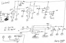
here - i've got a scanner - hopefully this helps. the lower left hand corner sums it up the best i can.
since i've terminated the inputs and outputs, this is all being tested on the bench without interconnects to another piece of gear. everything is seeing a happy load and such and such...
Attachments
Last edited:
A picture helps a lot! Personally, I would never connect the center-tap from the HT winding of the transformer direct to the chassis. That will be introducing noise from the charge current pulses that feed the capacitors.
The center-tap should go to the negative of the first filter capacitor only. Do not connect to the chassis at this point.
The negative of the first filter capacitor should go to the negative of the second. Do not connect to the chassis at this point
The negative of the second filter capacitor should go to the negative of the third. You can then take negative of the third filter capacitor directly to the star point. By the time you are on the third capacitor the current ripple is going to be very small.
That arrangement will keep the current pulses from the transformer and first and second filter stages out of the ground. But they must be wired in the right order as described.
Last edited:
Yes, folow 12E1's advice. Directly grounding the secondary CT is a very common mistake. However, the fact that you still see hum with the scope tip and ground at the same point suggests magnetic field induction as the main problem. Ensure that every grounded point in the system has one and only one path to ground. Ensure that forward and return currents, whether signal or PSU, are routed together and preferably twisted (unless using coax).
Hmmm. Posts #2 and #6 come to mind.
You previously refered to 5mV of 'observable' noise on the cro - and then you refered to 80dB of gain. But it doesn't seem like your 'noise' is coupling in to the amps signal path, but is rather an artefact of the CRO earth and amp combination. That's not to say that you don't have grounding problems, but more to clarify what can be gleaned from 'measurements', and how it can be difficult to separate the impact of the measurment technique.
Ciao, Tim
I appreciate the o'scope concern, but the audible noise I hear on each stage matches with the intensity seen by the scope, as well as a rough RMS AC measurement on the voltmeter. So, I'm confident in knowing that the scope isn't inducing the majority of this noise, or, perhaps, anything induced by the actual o'scope interaction with the preamp itself, since, if I listen while probing, I hear no or only a very, very, very slight change when I introduce the scope probe to various points.
Hum seen with the scope tip and ground at the same point means either a loop with magnetic coupling or a high ripple current being injected into what otherwise would be a good ground. Have you moved the transformer CT away from the star ground yet?
Yes - did that last night; put it right on the first filter cap's leads. I'd say there was a very small improvement in overall 'hash', actually.
And, yes, what I mentioned before is correct. I'm getting line frequency hum with harmonics (as you can see on the pictures). The 6SJ7 is set up for gain of ~120 and the EF86 for gain of ~80. Noise on 6SJ7 is 20mV and noise on EF86 is ~8mv.
I've done further troubleshooting:
Tried using unshielded interconnect cable. No change.
Relocated, or tried locally grounding input grids. Anything other than the star was much worse (to be expected). Tried slightly different 'nodes' for where the grid ground is connected; no change.
Re-looked at heater wiring placement, twisting, and pin connections. Everything looks good, heater wires are solid core heavy gauge, run close to chassis and away from signal and power lines... Will try a 'humdinger' pot next, since I can't seem to trace how this noise is entering the system - thoughts of it being induced by either mag coupling or perhaps AC induction are a good thought train...
I may now try to put the power transformer and power on a seperate chassis; although still not sure why. Both chassis' I've tried have both been aluminum.
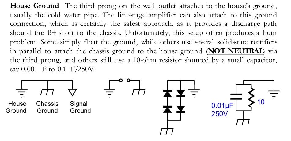
Tonight, I'm going to try doing a different connection to safety ground - through either the diodes or resistor/cap.
Can I provide anyone else any info?
Can't wait to find it out and add the knowledge to the database here.
i've tried multiple grounding schemes and considerations, which only bring the noise of the preamp down to the noise seen on the ground, as seen here. currently, i have a star ground. the first filter cap and PT center tap are tied together at one chassis point; all other points are star grounded together (each filter stage; each tube stages' cathode; each stages' grid; each stages' vol pot; anything being considered has an individual heavy gauge lead to star ground); further, the mains ground is connected through a short, heavy gauge wire at the mains input. no hum improvement tying the two ground points (PT/first filter and 'the rest) together.
(any thoughts of connecting the star ground to chassis via a 10 ohm resistor, or similar method, to help this out?)
2 questions:
When you say your noise is "on the ground" where is this referenced from i.e. where do you hook your scope probe ground clip to make this measurement?
At how many points do you connect "ground" to chassis? Especially the filter cap return connection, if separate fron the star ground, should not be connected to the chassis. Ideally there will be exactly one point where the star ground connects to the chassis. The only exception I make is the IEC power inlet ground, which can be lifted for testing.
PS I also would think DC heaters would be necessary but I haven't tried anything like this with AC heaters.
Last edited:
On your diagram, the input and output grounds both say "At Jack".
Are the input and output jacks isolated from the chassis? Or are the grounds connecting to the chassis, there?
Also, what is the noise level on the scope with the probe and probe ground connected across the output jack's signal connections, both with the input shorted and with the input open?
Are the input and output jacks isolated from the chassis? Or are the grounds connecting to the chassis, there?
Also, what is the noise level on the scope with the probe and probe ground connected across the output jack's signal connections, both with the input shorted and with the input open?
Last edited:
Noise on ground, of course there is.
And there is very little we can do about it...
There is a surprising lack of attention to AC entering the audio path at the first preamp stage(s). And this AC ingress is amplified thousands of times by the following stages.
In lower gain amps, this will be less of a problem, in high gain amps, it becomes a real headache.
Normally, the output tubes and phase inverter will function on AC heaters. It is the preamp stages, especially the first one or two, that deserve the most attention with a DC heater setup.
The best DC heater setup is probably in the old McIntosh tube hi fi preamp. The warmup of the heaters is slowed, but the reduced AC noise is more than worthwhile.
There are a variety of sources, that cause AC hum in the preamp, besides the heaters, and each one of these is worthy of it's own discussion.
1. The first most often ignored is the ceramic disk capacitors, and other components, in the audio path.
There type of capacitors can be the gateway for AC ingress (hum), to the audio path.
One good starting point is to replace these type of capacitors with a good grade of higher quality silver mica.
Yes - did that last night; put it right on the first filter cap's leads. I'd say there was a very small improvement in overall 'hash', actually.
That would be almost useless unless you ALSO fixed the rest of the filter caps' grounds, as described in detail by 12E1 in post 29, as follows:
"12E1 said: The center-tap should go to the negative of the first filter capacitor only. Do not connect to the chassis at this point.
The negative of the first filter capacitor should go to the negative of the second. Do not connect to the chassis at this point
The negative of the second filter capacitor should go to the negative of the third. You can then take negative of the third filter capacitor directly to the star point. By the time you are on the third capacitor the current ripple is going to be very small. "
And, yes, what I mentioned before is correct. I'm getting line frequency hum with harmonics (as you can see on the pictures). The 6SJ7 is set up for gain of ~120 and the EF86 for gain of ~80. Noise on 6SJ7 is 20mV and noise on EF86 is ~8mv.
What are the noise levels when measured between the grid inputs and the (local) input signal ground reference points (say, between the pot wiper lug and the pot ground lug, with maximum gain setting, for each stage)?
It would be helpful if you could do those measurement twice each: once with the input shorted and once with the input open.
I've done further troubleshooting:
Tried using unshielded interconnect cable. No change.
Relocated, or tried locally grounding input grids. Anything other than the star was much worse (to be expected). Tried slightly different 'nodes' for where the grid ground is connected; no change.
Re-looked at heater wiring placement, twisting, and pin connections. Everything looks good, heater wires are solid core heavy gauge, run close to chassis and away from signal and power lines... Will try a 'humdinger' pot next, since I can't seem to trace how this noise is entering the system - thoughts of it being induced by either mag coupling or perhaps AC induction are a good thought train...
I may now try to put the power transformer and power on a seperate chassis; although still not sure why. Both chassis' I've tried have both been aluminum.
Tonight, I'm going to try doing a different connection to safety ground - through either the diodes or resistor/cap.
Can I provide anyone else any info?
Can't wait to find it out and add the knowledge to the database here.
Yes. You need to get some photos of the layout and upload them. Perhaps a friend with a cellphone could snap some and email them to you on the spot.
- Status
- This old topic is closed. If you want to reopen this topic, contact a moderator using the "Report Post" button.
- Home
- Amplifiers
- Tubes / Valves
- Thoughts of apparent noise on ground - due to power tx?