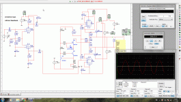
I have done some hobbywork tonight with some beer.
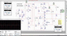
I have made a schematic of this, it looks a nice object for people here who wil try that, with the new sic jfets is it shure a nice object.
The mosfet driver tubes are the 6n6p or ecc99 versions, for the sic jfet I think we need some more muscles tubes, have you see the datasheet of the sic jfets
well let me know of it is worth the effort.
all here a happy new DIY year, and keep it sunstainable.
Attachments
Last edited:
Aren't you frying the power fets with 60V and some 2A current?
No the voltage between gate and source is 2.9 volt it is between the 220 ohm resistors, I have use the source as output, so it shoult be save. the 2 ampere is with load on 8 ohm and 125 watt output in simulation.
if tube voltage is gone, mosfets are shutt off, a speaker protection is here a big need while warming up the tubes, when cold there is no current between mosfets, that is a plus, but when a tube fail it will fry the speaker, so fuses is a good idea, bridge is more danger but I think it is for al types of amps, except single ones with output capacitor..
the pot on the ground between 125 plus and min voltage is for idle mosfets.
Maar ik denk dat je nederlander bent niet?
nog een gelukkig nieuwjaar.
Attachments
Last edited:
Ook de beste wensen Kees (Best wishes Kees)!
It seems you have 60 volts across each power fet and 2A of idle current; that is beyond their continuous power dissipation under practical circumstances even with huge heatsinks, but correct me if I am wrong.
You see the 2 ampere because I simulate high power on 8 ohm load, without the output it idle around 500 mA it can be adjusted with the pot.
It is suprisely stable with offset because the tubes are between gate and drain there the mosfet has no trouble with high voltage to some extent afcourse.
I am plan to try a power jfet here, but first other things otherwise I get stuck with all these ideas.
But pieter you have not hearing about circlotrons? the fets can stand 1 ampere each for class a, but is not my goal to get class a, so she will be idled on 400 mA each, some higher because of lack of feedback.
have a nice newyearsday, and welcome in the magic 2012.
Last edited:
Ah Kees, "only" 500mA is the idle current, that makes sense.
Yes I know circlotrons; actually I just started building a hybrid amp.
Design is a combination of Ciuffoli's hybrid circlotron and Susan Parker's Zeus.
Input stage will be D3a tube, with interstage / phase splitter transformer (I am a winder you know).
For the output stage I prefer Susan Parker's output transformer coupled Zeus design, as distortion is lower, damping better, power supply quite a bit simpler as only one + voltage is required instead of two floating + and - supplies, and no need for loudspeaker protection because of the OPT.
Last edited:
Ah Kees, "only" 500mA is the idle current, that makes sense.
Yes I know circlotrons; actually I just started building a hybrid amp.
Design is a combination of Ciuffoli's hybrid circlotron and Susan Parker's Zeus.
Input stage will be D3a tube, with interstage / phase splitter transformer (I am a winder you know).
For the output stage I prefer Susan Parker's output transformer coupled Zeus design, as distortion is lower, damping better, and no need for loudspeaker protection because of the OPT.
sound nice, But I hate windings it is personally, I am busy with a switched supply, here I have to put windings but is very small as het switching frequentie is high I use a chip NCP1200 to make a very simple smpt.
these is the amp I now use and playing here, with the 6N6p and 6H9C, also dc coupled to mosfets.
the sound? just listen, but is compressed by youtube.
http://www.youtube.com/watch?v=voklxcbYr_k
Attachments
Oke I have don again what tests with simulator.
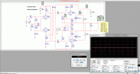
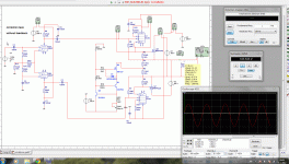
I have some questions, the tube drivers has to been able to give current fir the fet capacities, I used now 6N6P and in the simulations two EL84 penthodes in triode mode but what can this do, how low is the impedance of the triode strapped el84 as cathodefollower.
the grid negative voltage, how is best, or is this not important as cathode follower it is alowed to go plus and min, I ask this because my experience with it is not so big, have to learn,
One picture has two resistors extra to the grid 47k and and 33k, adjusting this so that negative can go up and down with current pot.
Or in other picture remove them and tie it two the 1.5k resistors, then it will always follow, and it see output voltage.
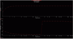
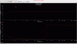
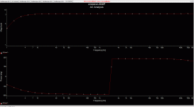
The ac is very good, the distortion also, 0.018, it go to 1 Mhz with EL84 in simulation, with 6N6P maybe even higher (lower Zout).
see the pictures
Attachments
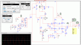
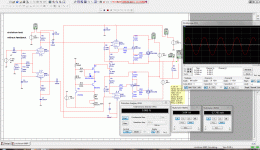
I have did some change, a pair extra fets to driver the power fets, then I can do use a small tube if I use low capacity mosfets.
idea behind this is the use of the power J-fets who need some juicy driver, I mean the new J fets from here. I can also test a bipolair driver with it later on, it is interesting to see how it will sound. The faseshift in ac simulation is not real, it has to do with simulator itselfs, in real it is not there.
I have no model for the j fets SJDP120R045 or others from there.
http://semisouth.com/wp-content/uploads/2011/05/DS_SJDP120R045_rev1.3.pdf
Attachments
- Status
- This old topic is closed. If you want to reopen this topic, contact a moderator using the "Report Post" button.
- Home
- Amplifiers
- Tubes / Valves
- hybride circlotron
