Dear All. I have tried my best and tried to come up with a way to use some GU81M I have seen lying around and *may* go and secure for future projects.
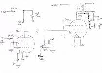
It is my very first attempt to create something. I have replicated the first stage from Pmillet's (813 SE triode amp) and tried to implement the alternative method of strapping a pentode into a triode (diodes and bypass caps on the right) but pmillet used a resistor in his design so I guess it is the correct approach (also with te B+ envolved I'd rather keep everything simple)")
I tried to do my best. It is probably just full of mistakes and useless but if anyone wishes to suggest a complete design I'd be grateful!
Alex
It is my very first attempt to create something. I have replicated the first stage from Pmillet's (813 SE triode amp) and tried to implement the alternative method of strapping a pentode into a triode (diodes and bypass caps on the right) but pmillet used a resistor in his design so I guess it is the correct approach (also with te B+ envolved I'd rather keep everything simple)
I tried to do my best. It is probably just full of mistakes and useless but if anyone wishes to suggest a complete design I'd be grateful!
Alex
Attachments
Dear All. I have tried my best and tried to come up with a way to use some GU81M I have seen lying around and *may* go and secure for future projects.
It is my very first attempt to create something. I have replicated the first stage from Pmillet's (813 SE triode amp) and tried to implement the alternative method of strapping a pentode into a triode (diodes and bypass caps on the right) but pmillet used a resistor in his design so I guess it is the correct approach (also with te B+ envolved I'd rather keep everything simple)
I tried to do my best. It is probably just full of mistakes and useless but if anyone wishes to suggest a complete design I'd be grateful!
Alex
1) Can you really ground the screen in the input tube? Will that work?
2) why not use a real triode as the input? Maybe you just happen to have this tube on hand? Triodes have lower noise.
3) Are you using an electrolytic cap as a coupling cap? That will not work. use a non-polarized type cap. Any film cap will do fine.
4) best to connect the wiper of the bias pot to one end. A common failure mode of pots is that the wiper goes open circuit. Then quickly after that the tube fails.
thanks ChrisA
1) NO. That was a stupid mistake. Obviously I need a source of +V and infact Pmillet's design has a +150v source and a 100ohm resistor in series.
2) Pmillet's original design had a 813 tube and required a suitable input tube to drive it. The characteristics I would be aiming for are: high gain, low impedance and (but can't tell by my own low distortion). Pmillet himself found out that video tubes provide all these characteristics in a package. Better than triodes infact!
also...(and It helps these days) the 12HG7 is quite cheap!
3)The decoupling cap should be non polarized. Forgot to write it down.
4) Thanks! Will redesign that part for sure!
However even If I get things going I am still stuck with finding adequate transformers.
SE transformers of 100+w need to be custom made I guess. I really don't know where to look. I'd rather have them made by someone I can trust and have a direct contact with.
Would the design work once the mistakes are corrected?
Do I need to ground the center tap between filaments?
Does the quality of the coupling cap have a really impact on the design? What would be a good choice?
Sorry for the dumb questions.
Alex
1) NO. That was a stupid mistake. Obviously I need a source of +V and infact Pmillet's design has a +150v source and a 100ohm resistor in series.
2) Pmillet's original design had a 813 tube and required a suitable input tube to drive it. The characteristics I would be aiming for are: high gain, low impedance and (but can't tell by my own
low distortion). Pmillet himself found out that video tubes provide all these characteristics in a package. Better than triodes infact!also...(and It helps these days) the 12HG7 is quite cheap!
3)The decoupling cap should be non polarized. Forgot to write it down.
4) Thanks! Will redesign that part for sure!
However even If I get things going I am still stuck with finding adequate transformers.
SE transformers of 100+w need to be custom made I guess. I really don't know where to look. I'd rather have them made by someone I can trust and have a direct contact with.
Would the design work once the mistakes are corrected?
Do I need to ground the center tap between filaments?
Does the quality of the coupling cap have a really impact on the design? What would be a good choice?
Sorry for the dumb questions.
Alex
Last edited:
...
Do I need to ground the center tap between filaments?
Does the quality of the coupling cap have a really impact on the design? What would be a good choice?
I just looked up the specs on a GU81M. This is NOT a project for a first time builder. Absolutely not. Once the B+ power gets over 1,000 volts you are in a different world. Kilovolt power supplies are like dealing with snakes, unpredictable and deadly and you don't get a second change after a mistake.
At first look i figured the gu81 was just a normal Russian beam tetrode like am EL34 or K66. But no, the thing is huge. Not at all the reasonable choice for a first time build.
One other problem. What is the input impedence of the power section? You have a 22K resister to ground on the grid. So the input is no higher than 22k. And what happens as you adjust the pot? At any setting other than full left it is less than 22k
Can your driver tube drive such a low impedance? I doubt it.
How will you build a power supply for this? What is the bias current in this tube. I'm guessing maybe 0.1 amp. There are no caps rated this high. You will need a huge series/parallel network and many equalization resisters.
Can you afford to have an output transformer designed and built. This will be in the "several hundred dollar" range and it will be truly huge in size and weight
I would not ground a filament. Best I think to elevate the entire heater loop. Make a virtual center tap and connect that to ground or to something above ground to elevate the loop.
There are people who will argue that only special ultra expensive coupling caps are any good. But, I think a more main stream opinion is that you will be fine as long as you don't use something really bad, like an electrolytic cap. Even if you do want the $100 cap, build the amp first with a normal $1 film cap.
Thanks ChrisA for your comment!
I have actually built several amps (mostly solid state) both in class A and AB. The last project is a 6 channel amplifier.
Tube world is different I know. To date I have built Pete's engineer's amp and small amps based on kt88 hence an interest in the new kt120s which caught my eye just like the GU81Ms
Some time ago I helped a friend build a teslacoil (incidentally that was the first experience with a vacuum tube) and even though I took no part in the design I did work with the thing for quite some time..building and testing all the power section.
I have tinkered with microwabe transformers, EAT transformers from old tv sets...always followed every safety procedure I could think of.
I am a newbie but this is not my first build.
To answer some of your questions to the best of my abilities:
1. To cover the B+ I will be probably go for several 4,700uf caps in series and resistors whith a secondary of 860v more or less. The remaining voltages will be derived from a common 380v secondary on the transformer. Filament voltage and relay control will be separate.
2. To answer some other points, a solution might be to insert an inline transformer (sorry if the term is not correct in english) between the driver section and the GU81M. A 1:2 or 1:3 transformer maybe?
This is just my first attempt at designing. If you were to design a schematic I would probably be able to build it.
Cost is a relative issue. I am willing to spend the necessary money. 100w - 150w is however my ultimate goal.
Alex
Thanks ChrisA for your comment!
I have actually built several amps (mostly solid state) both in class A and AB. The last project is a 6 channel amplifier.
Tube world is different I know. To date I have built Pete's engineer's amp and small amps based on kt88....
OK, yo understand then an ethical obligation to warn about 1,200 volt power supplies. I would contain all the 1,200 volt parts in an separate aluminum box. It is hard to even find connectors, fuses and even wire rated for such voltage. Although you can find these. Part of the fun is designing such that all failure modes fail in a safe way. For example when a fire happens because a cap exploded and the insulation melts off some hookup wire will 1,000 volts be exposed on one of the input jacks? So you need grounded sheet aluminum barriers so so on. Like I said 1KV power is a different world especially when yu think that one day this amp will be 20 years old and might fail but still needs to be safe even after some unpredictable failure like a shorted transformer or whatever.
But this still is a fun design.
I'm wondering about the output transformer. It is going to be huge. can such a large transformer still sound good on the high end? From my reading this depends mostly on the interleave plan and other details of the physical construction. Can anyone get this right on the first try? I don't know but I'd plan on a prototype or two.
They call these things "tube amps". I don't know why. Tubes are only a minor component. They should be called "transformer amps" because by far, the transformers are the largest, heaviest, most costly and the most critical to sound quality. The tubes are second place.
I certainly do!
However rest assured I do take all precautions I can when working with such equipment.
In my previous builds I have always used policarbonate to create layers, cages and /or sections to isolate various parts of the amp. In cramped spaces this works well. Plus you can find polycarbonate o similar products in most DIY stores. Easy to cut and to form with a small propane torch.
Anyways...back on topic.
Given adequate isolation and build characteristics, P-P transformers would be a better choice. It is not an impossible mission to find a 100w range P-P 5k transformer at a reasonable price. To find one with adequate isolation is another matter.
I have no theroetical basis to design an amp. I am just trying my best to learn so if some kind sould were to propose a P-P design based on the GU81M I would be grateful.
Alex
hey-Hey!!!,
I once thought to build with this tube...even got the tubes and sockets. What looked best before I came to my senses was a Class A PP design. U-L rigged; 20% tap location on. 800V supply, 400 mA idle per tube and a 3500 Ohm a-a output trans( to be capable of 200W full bandwidth ). OPT needed to be huge even then...I have since been playing with much smaller designs...
cheers,
Douglas
Bandersnatch...
Your input is appreciated.
I saw the Hammond 1650 series with OPT up to 280W RMS (12kg!!). Looking for something smaller one could opt for the 100w 5K PP OPT.
Or
Have them done (minimum 500$ expense) but may be worth it. I guess one could reasonably look for a 5K - 3.5K OPT rated at 200W RMS Big, sure, but mechanically doable.
I am really looking for info on a feasable design. Would a single driver stage work? is an interstage trafo absolutely necessary to couple the driver to the output section?
I really like a minimalist approach. All seems just so elegant.
The power section is not excessively complex, expensive, but not too complex.
By separating the filament heater trasnformer form the rest I may also cut down on the main transformer cost.
I really like the tubes. I have a photograph of them on my cellphone and they are just beautiful.
I will post a schematic later, maybe this time it will be better.
Alex
Ok. I guess 2/3 of the thread will end up being about how wrong this all is.
Let's just forget about it.
Sorry to the admins for having opened the thread.
Alex
P.s. just to be absolutely convincing, please try to scare people about current rather than voltage. 75mA through the heart's nerve clusters are far more scary than a 1200v or 2,5kv B+ line (even though there is an obvious correlation in terms of risk).
hey-Hey!!!,
There is nothing much safer about an EL84 amp v. one to be built around a GU81m. it is a matter of scale, and shade...
The 1650R would make a fine starting point. Work out the rest within that OPT's limits. You should be able to run 650V of B+ at what ever current level the OPT is rated for...and within reason probably 10% more.
Try EL84 as LTP for the input stage. Send me your email and I'll send you a scan of schematic.
cheers,
Douglas
- Status
- This old topic is closed. If you want to reopen this topic, contact a moderator using the "Report Post" button.
- Home
- Amplifiers
- Tubes / Valves
- First design GU81M SE triode