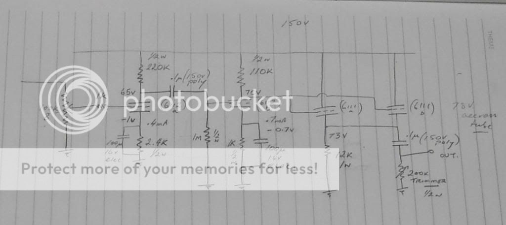
Had a go at designing a basic line level preamp to give me a taste of 'tube' sound with one 6112 front stage and a 6111 as a twin cathode follower, SY will love this.
Could have gotten away with using only one 6111 but decided on two, making the total complement 4 tubes for stereo operation, and seeing as I would like this portable, a 12V gel battery will power the heaters nicely.
Going by the data sheets I think I have everything close to right, although they could be totally wrong, anyone have any suggestions? Open for opinions on the HV supply from 12VDC.... I'm trying to follow the KISS principle on this one, no SS, single end. Nice and simple with reasonable sound......
Sorry about the photo, no scanner at the moment so used my camera...
Cheers")
Could have gotten away with using only one 6111 but decided on two, making the total complement 4 tubes for stereo operation, and seeing as I would like this portable, a 12V gel battery will power the heaters nicely.
Going by the data sheets I think I have everything close to right, although they could be totally wrong, anyone have any suggestions? Open for opinions on the HV supply from 12VDC.... I'm trying to follow the KISS principle on this one, no SS, single end. Nice and simple with reasonable sound......
Sorry about the photo, no scanner at the moment so used my camera...
Cheers
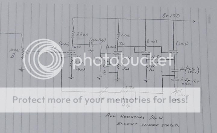
Hi DF96, yeah I was going to include a small feedback loop from the cathode follower back to the first grid to ease the amplification. Attached is a pic with the changes....What do you think? I have built just about everything else in the past on 12AX7 phono circuits, hence the high gain....
Haha yeah I'm a bit new to this, designing circuits from scratch is completely different to just wiring one up from a schematic. Please bear with me
Basically what I'm looking for is a small tube sounding in line preamp, that can safely satisfy relative high impedance input and a fair whack of current out. I thought I'd throw together a more simplified version, see attached. I'm using the 6112 for voltage gain and the 6111 as a cathode follower because of it's much higher current rating. I know you have a thing for CFs so If you don't like my way of doing it please offer a better solution. I personally think they have great potential.... even if I possibly have it clipping on the output sometimes due to poor design on my part.....

Basically what I'm looking for is a small tube sounding in line preamp, that can safely satisfy relative high impedance input and a fair whack of current out. I thought I'd throw together a more simplified version, see attached. I'm using the 6112 for voltage gain and the 6111 as a cathode follower because of it's much higher current rating. I know you have a thing for CFs so If you don't like my way of doing it please offer a better solution. I personally think they have great potential.... even if I possibly have it clipping on the output sometimes due to poor design on my part.....
I can honestly say that I don't recall seeing another tube line stage quite like it. The topology is more like what one would find in an low impedance feedback phono stage, or in a solid-state linestage.
By the way, John Broskie has an absolutely fantastic tube circuit design & education website. John has many great novice tutorials published there, including on cathode followers . He also offeres tube circuit CAD software, and sells inexpensive kits of many of the circuits presented. If you never have before encountered John's "Tube CAD Journal" website, and are interested in learning the basics of tube audio circuit design, you're in for a real treat.
http://tubecad.com/
Last edited:
I know you have a thing for CFs...
If by that you mean "I think they are often designed poorly, but can be designed superbly," then yes.
The cathode follower you have shown is problematic...Question 1 is still: what gain are you targeting? For most modern sources and modern power amps, you don't need more than unity gain. If that's the case, we can design an excellent cathode follower quite easily.
On close inspection I have put those resistors around the wrong way in the cathode, so yes I would be getting about -50 volts bias there.......point well received. O.k gain question: Unity for now. I was hoping to have a basic circuit that could be adapted nicely for phono, mic, unity...later down the track. But please do tell about an excellent cathode follower unity circuit SY
O.k gain question: Unity for now. I was hoping to have a basic circuit that could be adapted nicely for phono, mic, unity...later down the track. But please do tell about an excellent cathode follower unity circuit SYThanks for the link Ken, I guess you could say that it's unique! haha. Funny thing is I made a 12AX7 preamp several years ago using close to the same design and it sounded terrific. (to my ears anyway)
I believe that the primary thing which matters about the circuit is how it sounds to you. We don't listen to music through a spectrum analyzer, we listen to it through our own ears.
True Ken, I used a MC275 amp as a reference when testing, and even though I might have been a little 'biased' towards my build, I'm sure the sound was pretty good.I believe that the primary thing which matters about the circuit is how it sounds to you. We don't listen to music through a spectrum analyzer, we listen to it through our own ears.
But please do tell about an excellent cathode follower unity circuit SY
http://www.syclotron.com/?page_id=8
While you may or may not not want to copy this set of designs, this should at least be useful to show how a good unity gain preamp can be done. The circuits could easily be adapted to 6111- I'd use one tube (two sections paralleled) per channel, with 90V plate supply and 10mA CCS. I've been using different versions of this preamp in my system for some years now- currently a six channel version for my triamped system. If I were to do it again from scratch, I might use a simpler CCS arrangement (cascoded DN2540), but for lowered parts count, not performance.
Thanks SY, I checked out your circuit and just have a couple of questions... The CCS on the cathode, what exactly does this achieve?, I'm sure the answer is improved linearity, cathode biasing and so on, however could you clear these up for me, and how does this design improve on typical resistor or inductor cathode?SYclotron Audio The Heretical Preamp
While you may or may not not want to copy this set of designs, this should at least be useful to show how a good unity gain preamp can be done. The circuits could easily be adapted to 6111- I'd use one tube (two sections paralleled) per channel, with 90V plate supply and 10mA CCS. I've been using different versions of this preamp in my system for some years now- currently a six channel version for my triamped system. If I were to do it again from scratch, I might use a simpler CCS arrangement (cascoded DN2540), but for lowered parts count, not performance.
I saw another CF on an aikido site, using two potions of the triode in series. This makes sense to ensure a very flat frequency response but uses no SS devices.... Thanks for bearing with me, I guess you get asked these questions every year, year after year....
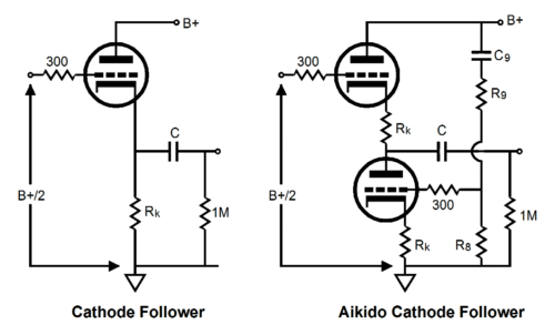
Yes, cathode biasing. However, if you use a big resistor for the same nominal current, let's see what happens:
Say we have an ECC88 biased for 10mA. We have a 200V supply and raise the cathode to 100V. We then need a 10k resistor, which sets the baseline linearity (the lower the load resistance, the higher the distortion). If we drive a 10k load at the far end, the tube is now loaded with 5k at AC. Distortion will be higher. Mind you, it still won't be high and it will likely still be below the threshold of audibility, but just in case...
When you stack two triodes like that, you have (putting aside the noise nulling bits) the same CCS loading, just with a lousy CCS and the complication of having to deal with heater-to-cathode voltage issues. It still works quite well, but as I showed in my article, very rudimentary techniques get the noise so low that the nulling bits aren't really necessary. One could apply them to the bipolar CCS as well, if desired, but... The principal advantage is esthetic- some people hate the idea of transistors anywhere in the circuit, even where they are being used as constant voltage sources or constant current sources.
So does that mean a CCS in the cathode gives us something comparable to a choke? relatively high AC impedance?
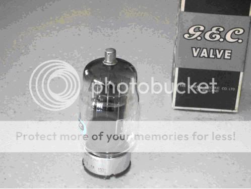
I'm still a little unsure as to how the grid biases in relation to this CCS in the cathode....... Also why I have your attention, does this look like a NOS TT21? can get them pretty cheap, and would make a nice PP. I am asking because the getters look a little dark.....although this could be straight from the factory like this, If really NOS then bargain at $85 each.
I'm still a little unsure as to how the grid biases in relation to this CCS in the cathode.......
Also why I have your attention, does this look like a NOS TT21? can get them pretty cheap, and would make a nice PP. I am asking because the getters look a little dark.....although this could be straight from the factory like this, If really NOS then bargain at $85 each.
You can get much higher impedance (and more ideal behavior) from a CCS than form a choke in this sort of circuit. Not to mention an order of magnitude lower cost for the increased performance. As well, the CCS provides DC bias automatically, whereas a choke, not so much.
I've never used a TT21, but I wouldn't let a dark getter worry me- the tube may or may not be good irrespective of the getter color. Unless the getter is white, in which case, yeah, there's a problem.
I've never used a TT21, but I wouldn't let a dark getter worry me- the tube may or may not be good irrespective of the getter color. Unless the getter is white, in which case, yeah, there's a problem.
Ok I think I'm getting this now, for the CCS or resistor/choke to work properly it would ideally need to connect to a voltage rail below the GND. In your circuit it seems -12 rail it this correct?. I saw in old Mcintosh circuits the grid bias was provided directly from the plate in the previous section ( not applicable here) they seemed to have used this in the c22, and C2200 but not in the C22 anniversary edition where it looks as if they have cap coupled the previous stage and then created a bias with two resistors in series off the HT. I can't help but think this would introduce PS hum or something....... Just one last question, as the grid signal changes the "resistance" (for simplicity) of the tube, on a conventional cathode follower the resistor would exhibit a voltage swing, Hence signal re-production. However how does a a CCS reproduce this when as the resistance of the tube changes, the CCS internal resistance accommodates to keep the current consistent, (hence the title) does this mean the swing is only measurable between the cathode and GND and not the cathode and -12 Volts. Oh and what do you think about using the TT21 as replacements for a MC275? I was thinking of modifying octal socket savers to include a plate lead. Seeing as NOS GEC KT88 are abouts $400 each, I figure this is a very reasonable way to get that "NOS" sound for cheap
Oh and what do you think about using the TT21 as replacements for a MC275? I was thinking of modifying octal socket savers to include a plate lead. Seeing as NOS GEC KT88 are abouts $400 each, I figure this is a very reasonable way to get that "NOS" sound for cheap - Home
- Amplifiers
- Tubes / Valves
- 6112 and 6111 Mini-preamp