It is feasible in the sense that it will amplify audio signals. Possibly sub-optimal in the sense that a simple active load for the first triode would probably work just as well.
Driving an EL34 ultralinear output could require the phase splitter to use a significant part of its characteristic, so some distortion could occur here.
Driving an EL34 ultralinear output could require the phase splitter to use a significant part of its characteristic, so some distortion could occur here.
It is feasible in the sense that it will amplify audio signals.
not that I know much about it
but when using the low side out output of the mu-follower, which is high impedance, is there something about loosing gain, when 'receiver' load is less than in the mega ohm range
'upper' output on mu-follower is of very low impedance, and thus not a problem
but high impedance low side might be used fore DC coupling
why that is I dont know
Actually the output impedance of the lower output is "higher", not too high. About 12K in this case. The input impedance of the cathodyne is very high so the gain of the 12AT7 should not be affected.
Last edited:
how do calculate/choose the right phase splitter tube, to ensure good balance between anode and cathode ?
(honestly I dont understand why theres not more gain from upper anode side, but apparently both sides are unity gain)
I understand that the limited drive of cathodyne phase splitter can be ok with easier driven tubes like el84
but EL34 can be a bit more tough to drive, or ?
also, cathodyne phase splitter might be more easily 'overdriven', from what I have read
considering the very high gain of mu-follower, would this cause 'issues' ?
how do calculate/choose the right phase splitter tube, to ensure good balance between anode and cathode ?
(honestly I dont understand why theres not more gain from upper anode side, but apparently both sides are unity gain)
I understand that the limited drive of cathodyne phase splitter can be ok with easier driven tubes like el84
but EL34 can be a bit more tough to drive, or ?
also, cathodyne phase splitter might be more easily 'overdriven', from what I have read
considering the very high gain of mu-follower, would this cause 'issues' ?
The Morgan Jones book suggests a low mu tube for better output balance. Other sources suggest this as well.
There may very well be too much gain in the mu-follower. It is direct coupled through a voltage divider to match the calculated grid bias of the phase splitter. The 6N1P is pretty much pushed to the limit in this case, and may not (probably won't) drive the EL34s very well at all. Another stage could be added. But this is an experiment.
Here is a good article by Albert Preisman: http://www.aikenamps.com/cathodyne.pdf
If you are going to use a 6N23P, why not use both stages for the Mu Stage as it is designed for Cascode operation per the data sheet.
My thinking was that the higher mu of the 12AT7 would provide better gain. But you may be right.
In this phase splitter circuit balance comes simply from having equal loads on cathode and anode. As both are the same total impedance and carry the same current they develop the same voltage. The voltage gain is a bit less than one.tinitus said:how do calculate/choose the right phase splitter tube, to ensure good balance between anode and cathode ?
(honestly I dont understand why theres not more gain from upper anode side, but apparently both sides are unity gain)
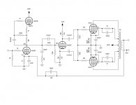
I'm sure this has been done before, but does it look feasible?
Scott
Feasible? Yes. However, there are a number of problems with that design.
1) That Mu-Stage up front: you'd be better off replacing that with a solid state CCS. The Mu-Stage was originated back in the days when good solid state components didn't exist yet. There are better solutions.
2) You have a high gain stage up front, then throw away over 3.0dbv of that gain across that voltage divider. That's nuckin' futz.
3) Can your cathodyne drive Ultralinear 6CA7s? The cathodyne has a serious drawback: limited swing for the Vpp. Operating in pure pentode mode usually presents a friendlier load (less required input swing, less Ci).
4) No gNFB: a PP amp that uses pents on the back end will probably need gNFB to sound really good. Local NFB (and that's what Ultralinear is) can do only so much. It helps tame the more difficult pents (6L6/807) but may or may not be required for others (e.g. 6V6, 6BQ6). But still, open loop operation is mainly for triode only designs.
5) Capacitor coupling to the finals isn't my first choice since it could present a problem with blocking distortion. Ditto cathode bias on the finals. I prefer fixed bias there for lower distortion.
how do calculate/choose the right phase splitter tube, to ensure good balance between anode and cathode ?
As for choice of cathodyne splitters, it's not really a critical application. The main thing is selecting a type that can provide adequate drive to its loads. Types like the 6C4, 6J5, 6FQ7, 12AU7, 12AT7 (one section, or both paralleled) or pseudotriodes made from types like the 12BY7A (or even full-on pentode operation of the 12BY7A with separate, floating screen supply) all make very good cathodynes). What you don't want to use is something like a 12AX7, 6SL7, or some other low current triodes.
As for calculations: same as always: loadlines.
(honestly I dont understand why theres not more gain from upper anode side, but apparently both sides are unity gain)
So long as there is but one current path, and for every triode: Ip= Ik, then the voltage drops across the plate and cathode load resistors must be equal. It only goes out of balance if one load pulls more current than the other. Then the nasty distortion resulting lets you know to back off on the volume.
Last edited:
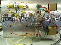
I have attached the circuit I ended up building. I've been wanting to try an input stage like shown, and I am not disappointed. Sounds great so far. I did not use gNFB. The values shown on the schematic (for gNFB) are arbitrary and I'm sure not accurate at all. I also did not use the RC compensation prior to the voltage divider input to the cathodyne phase inverter.
I raised the heater reference voltage for the driver and cathodyne up about 45V.
The question was posed, "Can the cathodyne directly drive 6CA7s connected ultralinear?" It appears to do just fine. The 6CA7s clip before the driver or the cathodyne.
With a tone generator connected, I am getting a flat response at the output from about 8Hz to 58KHz.
A couple of issues though:
1. The B+ is lower than I calculated. Right now about 375V. I am using a 5U4GB. I have ordered a 5AR4. From what I understand the 5AR4 will bring the B+ up about 30V.
2. The PT I had available is only 200mA, so I had to bias the 6CA7s pretty light. I need to take operating current measurements and see if I can push them a little harder. Ultimately a new PT when I can afford it.
With this current configuration I get about 35V P-P at the output right before clipping. Hopefully the higher B+ will help. I suppose I could wire it pentode and see what I get. But right now it sounds very good.
The hum measured at the output is about 1mV RMS.
I want to thank Miles Prower for his input, and also TheGimp for suggesting to use the 6N23P for both sections of the driver. Worked out great. I am using an EH 6922, which is modeled after the 6N23P.
Thanks,
Scott
Attachments
Last edited:
With the global feedback removed by the first stage cathode capacitor you don't need the feedback network or the compensation network. If you re-introduced the feedback then the compensation network would need to be changed to match the change in anode impedance caused by the change in valve.
I'm puzzled by the bypass caps on the screen resistors - won't they undo their function as stoppers?
I'm puzzled by the bypass caps on the screen resistors - won't they undo their function as stoppers?
I believe I read in Radiotron that a small value cap across the screen resistor would help to eliminate stray RF. It is only 100pF. I may be totally wrong on this, but I had the caps so I thought I would try it. Of course it does go against my own "less is more" approach. I suppose I should remove them and see if it makes any difference at all. As it is right now, zero global feedback and no compensation network seems to work quite well.
Last edited:
I would have thought that caps bypassing a stopper are more likely to cause a lot of stray RF! UL outputs can easily turn into a push-pull oscillator.
Nope.
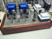
The more I listen to this amp, the more I like it. But isn't that always the case?
For this amp, I believe the mu stage driver really makes a difference. I realize that many here say there are better and more modern (solid state CCS) ways to do this, but hey, at the end of the day it's all about how it sounds to "me" right? I'm not deaf. I like zero silicon. The last time I checked I was good up to about 18KHz. Not bad for an old guy. I have built the tubelab.com 100W version of Millett Engineer's amp and it's really great for a party! Excellent bass and overall response. I also have built (and sell) a KT88 SE. This version of a 6CA7 PP amp probably falls between the two, sounds great, a bit more detailed than the Millett, but so far the KT88 SE is my absolute favorite without question. I have compromised on the power supply for this amp just because of the parts I had available. I'm confident that with the proper PT to adequately power the circuit, that this is a real contender.
For this amp, I believe the mu stage driver really makes a difference. I realize that many here say there are better and more modern (solid state CCS) ways to do this, but hey, at the end of the day it's all about how it sounds to "me" right? I'm not deaf. I like zero silicon. The last time I checked I was good up to about 18KHz. Not bad for an old guy. I have built the tubelab.com 100W version of Millett Engineer's amp and it's really great for a party! Excellent bass and overall response. I also have built (and sell) a KT88 SE. This version of a 6CA7 PP amp probably falls between the two, sounds great, a bit more detailed than the Millett, but so far the KT88 SE is my absolute favorite without question. I have compromised on the power supply for this amp just because of the parts I had available. I'm confident that with the proper PT to adequately power the circuit, that this is a real contender.
Last edited:
The more I listen to this amp, the more I like it. But isn't that always the case?
No it's not always the case. Listening to a new circuit right now....... the more I listen the more I feel like killing someone. Congrats on your build.
- Status
- This old topic is closed. If you want to reopen this topic, contact a moderator using the "Report Post" button.
- Home
- Amplifiers
- Tubes / Valves
- Mu Follower Driver for Push-Pull