Hi Everybody !
I wanna ask You: have somebody some infos for Audio Note P-zero monoblocks?
Schematics, inside pohotos, etc.
Audio Note
I wanna ask You: have somebody some infos for Audio Note P-zero monoblocks?
Schematics, inside pohotos, etc.
Audio Note
Last edited:
Do please excuse me; I naively assumed that publishing a copyright schematic was indeed the issue and against the forum rules- I really must read them more carefully.
What I DO know, however, as the Director of Audio Note is a friend of mine, is that they are very open and approachable and welcome any interest in their products. Peter Qvortrup would almost certainly provide a schematic for personal use.
What I DO know, however, as the Director of Audio Note is a friend of mine, is that they are very open and approachable and welcome any interest in their products. Peter Qvortrup would almost certainly provide a schematic for personal use.

Nowhere does mayky say he has a P-zero. Many of us are interested in how commercial equipment is built, either for the design ideas or to make our own (for personal use) "replica". I can see nothing wrong with that.
The only issue may be publishing a copyright schematic.
There is virtually nothing new in vacuum tube schematic since 50 - 60 (only hybrid amps are exception). Small tweaks don't need to be counted as real invention.
Even if something was patented/copyrighted, it is expired due to the age.
patenting and copyrighting are hardly the same thing though, wouldn't you agree?
Yes, but none of it can be violated neither for personal neither for commercial purpose.
Original (non-derivative) schematic made with some unique features/algorithms can be patented (its quite expensive process, however,), visual look (if really different from anything else on the market) is copyrighted from the moment of creation.
When it comes to vacuum tube schematic, it can be copyrighted only as picture (drawing, artwork, call it as you like), but it can't be patented because it simply put, typical, and similar solutions exist for over half of century in sheer numbers.
Original visual design (e.g. Wavac, Lars) is also subject of copyright. AuidoNote is not because it is typical for this product range, and many of this company products use industry-standard OEM boxes/enclosures.
Scanned AudioNote vacuum tube schematic can't be posted on forum because it is copyrighted material. However, you can redraw it with any software or just by hand and post anywhere.
http://www.audiofil.net/data/upload/20060522_172303_pzero_be099.jpg
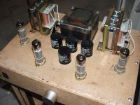
Apparently installation is similar to this one.
http://farm4.static.flickr.com/3013/2888183044_e464ac3463.jpg
Apparently installation is similar to this one.
http://farm4.static.flickr.com/3013/2888183044_e464ac3463.jpg
Last edited:
http://www.audiofil.net/data/upload/20060522_172303_pzero_be099.jpg
Apparently installation is similar to this one.
http://farm4.static.flickr.com/3013/2888183044_e464ac3463.jpg
Thanx. I-Zero and P-zero.
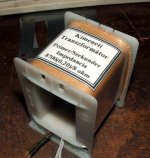
I have some russian tubes too 6Ф3П, winged logo C the original Svetlana
")
Hi Mayky,
The AN P-Zero mono blocks delivers 8 Watt each from a pair of ECL82 tubes, where the pentode sections runs in ultra linear (20% taps) push-pull output stage, and one triode section acts as input amplifier and the other triode acts as a phase splitter (but I think they use a driver transformer for this job).
So this is a simple, well understood, and widely available schematic in the internet, BUT with a few variants.
AN UK design is very specific in the way they tap the primary output transformers at 20% to connect the screen grid to get the most power and low distortion from the tubes in class AB2 (I don't think they can take 8 Watt in class AB1, so I believe they use a drivers transformer to run them into class AB2.).
Most of the transformers are tapped at 43% as this is a more common value.
The primary impedance should have a minimum of 9Kohm.
Also our own site refers to this issue before, here:
http://www.diyaudio.com/forums/tubes-valves/63441-ecl82-6bm8-pp-stereo.html


So, You really need the correct driver and output transformers to get the most from your tubes and reach the specified power and distortion.
I believe AN in UK will be happy to sell you the transformers and the schematics as well, I'm sure.
http://www.audionote.co.uk/articles/reviews/ANote.pdf
http://www.audionote.co.uk/downloads/zero_manuals/an_p_zero.pdf
Also you may like to check this transformer manufacturer in UK:
SOWTER AUDIO TRANSFORMERS
The AN P-Zero mono blocks delivers 8 Watt each from a pair of ECL82 tubes, where the pentode sections runs in ultra linear (20% taps) push-pull output stage, and one triode section acts as input amplifier and the other triode acts as a phase splitter (but I think they use a driver transformer for this job).
So this is a simple, well understood, and widely available schematic in the internet, BUT with a few variants.
AN UK design is very specific in the way they tap the primary output transformers at 20% to connect the screen grid to get the most power and low distortion from the tubes in class AB2 (I don't think they can take 8 Watt in class AB1, so I believe they use a drivers transformer to run them into class AB2.).
Most of the transformers are tapped at 43% as this is a more common value.
The primary impedance should have a minimum of 9Kohm.
Also our own site refers to this issue before, here:
http://www.diyaudio.com/forums/tubes-valves/63441-ecl82-6bm8-pp-stereo.html
So, You really need the correct driver and output transformers to get the most from your tubes and reach the specified power and distortion.
I believe AN in UK will be happy to sell you the transformers and the schematics as well, I'm sure.
http://www.audionote.co.uk/articles/reviews/ANote.pdf
http://www.audionote.co.uk/downloads/zero_manuals/an_p_zero.pdf
Also you may like to check this transformer manufacturer in UK:
SOWTER AUDIO TRANSFORMERS
- Status
- This old topic is closed. If you want to reopen this topic, contact a moderator using the "Report Post" button.
- Home
- Amplifiers
- Tubes / Valves
- Audio Note P-zero