Al the same. For distortion: Triode SRPP still the limiting factor.
We need to do something to further stiffen current there, to let
Mu give us as much linearity as it possibly can.
I ponder again JFET current diode for R5? Blew simulated smoke
in my sim, but I had also sabotaged cathode bias to only watch
the 470R. So was my own fault, and my own misinterpretation
of a damaging result... I think it would live OK in your original.
replaced IRFP240/IRFP9240 with 2SK1529/2SJ200, the THD drops from 0.08% to less than 0.05%! Keppeter is correct, Nothing special with IRFP240/IRFP9240. Audio MOSFETs are far better than IRFP. The sound is quite good, even better than my previous JLH amplifier. I like it's medium to high freq performance, very warm and clear.
My simulated distortions are much larger than your real ones.
I do not know if I can draw valid conclusions from simluation?
But I did run some ideas for stiffening the SRPP current. I get
the lowest simulated distortion when current in T1A's plate is
held the most constant.
I can't yet recommend the current diode for R5, because these
jfet diodes need 10VDS to actually become constant. Else they
are just a resistor, perhaps no better or worse than R5...
I tried replacing the entire top with 22K + 4.7u + 22K bootstrap.
And this provided extremely stiff loading, but made T1A deliver
plate current swing into the MOSFET, proved counterproductive.
I tried an even 3 way split with 470R cathode resistors, and 22K.
This worked almost the same as 2K2 cathode without bootstrap...
The big cathode resistor was important, giving it up was a prob.
Then I tried some slightly uneven splits, to keep as much cathode
resistance under T2A as would still allow for a bootstrap above.
I can persuade simulated distortion down about half, this way.
No idea what that might translate in real life...
The bootstrapped gain is considerably higher, so the inputs were
adjusted to normalize outputs at 50VPP for a fair comparison.
----
My MOSFETs are IRF243 and 2N6804 (w.IR and CCBS JANTX logos).
I have no idea if these big TO3's are suitable for audio, they been
on a huge heatsink with crazy poisonous Beryllium spacers, waiting
a project for years...
I got a few pairs of 24V switchers... The triode might want a pair
of 6V and 4V transformers, back to back for isolation???
Attachments
Last edited:
Am I fooling myself the distortion is slightly lower without R5's bypass cap?
The gain is slightly lower, but I normalize for equal output when I compare.
Miller is rolling off at 60KHz with only the big resistor driving T1B grid, and
I think the small gain loss here is purely resistive...
Even so, the modified gain is still higher than original SRPP plate loading.
The current diode has 12V to play with when biased as shown. And twin
triodes get about an even split of the voltage left over, at 5.75mA.
I am hoping reductions in simulated distortion will reduce real distortion,
even though real figures are already much less than expected. It makes
sense that we want T1a plate currents to be very stiff, and voltage swing
upon its unbypassed 390R or 470R cathode resistor R6 to be negligible.
Not sure which value for R6 will split the real voltage more evenly?
Experiment might have to tell...
-----
High (Transconductance / QGD) audio grade MOSFET might be
desirable for the N-CH, to limit the load placed upon T1B's cathode.
I don't think the P-CH need be anything special, its so well driven...
And they definately won't need to be matched compliments, as the
current sensing resistors and Q3 have already enforced virtual match.
Attachments
Last edited:
New years gift has arrived...
Box was basically a destroyed mess with giant hole in the
side, stamped "recieved in damaged condition" by customs.
But everything inside was thickly wrapped in bubble sheet.
And even the glass tube (wrapped separately) appears to
have survived the rough trip. No problems. All good.
-----
I'll take with me to work tomorrow. But I don't think I'll be
spending much time in my own lab where I can mess with it.
I'm scheduled to be over at TI, testing EVMs with TI chips
for cell phones. That will probably take all day...
Sometime this week I do want to power it up and measure.
Also interested to Xray this triode to see what structure is
hiding inside...
Last edited:
Not for TI directly. But I have a contractor badge that gets me in the door.
Anyways, I found some problems in the DC check, before attaching a load.
There was 2.8V DC offset at the output! The pot must have got knocked
out of alignment by the shipping? Anyways, that was quickly put right...
No speakers were harmed.
More disturbing, I found -1V DC offset at the input! Clearly, the grid leak
resistor is too big. I put a 600ohm attenuator across the input for now...
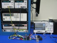
I measure 1.6A quiescent. Was expecting higher. This is not going to take
an 8 ohm load beyond 12.5V . With 24V rails, that seems a bit underkill?
Its gonna current clip before it gets halfway to the rail. Your intentions
were aimed at a lower voltage, like +/-15V perhaps?
All in all, I don't see any major issues that can't be fixed. Music sounded
quite good, given the quiescent operating point has not been optimized.
The plates draw less than 1mA, and that too seems quite low. Would be
the power supply on the bottom of the rack. Does not trip the last digit
except when the cap is first charging up, that one I had limited to 15mA.
There might also be issue with touching the blue mat. I need to put some
legs and get the high voltage parts up off the anti-static surface.
The filaments are on 6.3VAC, by the way. That's not DC you are seeing.
I measured 82VDC heater float, seems almost ideal, heard no 60Hz hum.
This photo was taken at my lab, not at TI. This is our high voltage work-
station where PFC correction stuff is sometimes tested. I borrowed some
stuff from one of the audio workstations, pardon the mess...
Anyways, I found some problems in the DC check, before attaching a load.
There was 2.8V DC offset at the output! The pot must have got knocked
out of alignment by the shipping? Anyways, that was quickly put right...
No speakers were harmed.
More disturbing, I found -1V DC offset at the input! Clearly, the grid leak
resistor is too big. I put a 600ohm attenuator across the input for now...
I measure 1.6A quiescent. Was expecting higher. This is not going to take
an 8 ohm load beyond 12.5V . With 24V rails, that seems a bit underkill?
Its gonna current clip before it gets halfway to the rail. Your intentions
were aimed at a lower voltage, like +/-15V perhaps?
All in all, I don't see any major issues that can't be fixed. Music sounded
quite good, given the quiescent operating point has not been optimized.
The plates draw less than 1mA, and that too seems quite low. Would be
the power supply on the bottom of the rack. Does not trip the last digit
except when the cap is first charging up, that one I had limited to 15mA.
There might also be issue with touching the blue mat. I need to put some
legs and get the high voltage parts up off the anti-static surface.
The filaments are on 6.3VAC, by the way. That's not DC you are seeing.
I measured 82VDC heater float, seems almost ideal, heard no 60Hz hum.
This photo was taken at my lab, not at TI. This is our high voltage work-
station where PFC correction stuff is sometimes tested. I borrowed some
stuff from one of the audio workstations, pardon the mess...
Attachments
Last edited:
I measure 1.6A quiescent. Was expecting higher. This is not going to take
an 8 ohm load beyond 12.5V . With 24V rails, that seems a bit underkill?
Its gonna current clip before it gets halfway to the rail. Your intentions
were aimed at a lower voltage, like +/-15V perhaps?
Nothing wrong with 1.6A quiescent for 8 ohm load with 24V rails.
Silly math error on my part. Quiescent implies 3.2A peak, which is
just fine...
Last edited:
- Status
- This old topic is closed. If you want to reopen this topic, contact a moderator using the "Report Post" button.
- Home
- Amplifiers
- Tubes / Valves
- Playing with hybrid amp: SRPP + MOSFET