I know this question has been asked before, but I've found the hundreds of pages of discussion to be confusing...
I am wanting to rebuild the filament supplies in my 300B amps. Currently, they use the 5V tap into a bridge rectifier, into a Xicon 10,000uF 16V cap, into a 0.8-ohm resistor, and into another Xicon 10,000uF 16V cap.
I have the following limitations:
* There is limited space available in the amp chassis, so I cannot fit in a large inductor.
* I don't have enough voltage, nor space for another transformer, to allow a regulated supply.
I am hoping to use Schottky diodes into a higher quality capacitor, then into an inductor, followed by more high-quality capacitance. But, I don't know which parts would be best... Do you have any recommendations for the Schottky's, caps, inductors, etc?
Thanks all!
Hi,
Links to vendors are provided for convenience and consist neither recommendation or endorsement in any way of the vendor, only of the specific part. Generally parts of comparable quality and rating can be substituted.
Diodes:
4 pcs of 31DQ04 assembled as discrete bridge.
In theory you can solder them directly across the old Bridge rectifier, their lower flow voltage will effectively "hog" all the current and disable the original bridge, doing it properly and using a small vero-board looks cleaner and gives more satisfaction of a job well done.
Capacitors:
1st Cap Nichicon FW 10,000uf / 25v
2nd Cap Nichicon UFW 33,000uf / 10v
Choke:
This needs looking at what parts you can get where you are.
The choke needs to be rated for 1.5A to 2A DC and reasonably low DCR.
I would suggest using 2 pcs, one in each line of the supply (Positive & Negative) and adding a resistor between bridge and the first capacitor to fine-trim the voltage.
For example the API Delevan 1,000uH/2.4Amps/0.235 Ohms has suitable ratings...
Two in both legs give effectively 2mH inductance with 0.47 Ohm DCR. It would be nice to have more inductance, but the needed chokes may be hard to come by...
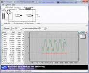
You can easily sim the resulting PSU in PSUD, I did quickly and I get 9mV RMS (26mV Peak-Peak) remaining noise with a nice sine wave shape, indicating the absence of higher mains harmonics. The remainder should null out nicely using a normal hum bucker pot.
Ciao T
Do you have any recommendations for the Schottky's, caps, inductors, etc?
Links to vendors are provided for convenience and consist neither recommendation or endorsement in any way of the vendor, only of the specific part. Generally parts of comparable quality and rating can be substituted.
Diodes:
4 pcs of 31DQ04 assembled as discrete bridge.
In theory you can solder them directly across the old Bridge rectifier, their lower flow voltage will effectively "hog" all the current and disable the original bridge, doing it properly and using a small vero-board looks cleaner and gives more satisfaction of a job well done.
Capacitors:
1st Cap Nichicon FW 10,000uf / 25v
2nd Cap Nichicon UFW 33,000uf / 10v
Choke:
This needs looking at what parts you can get where you are.
The choke needs to be rated for 1.5A to 2A DC and reasonably low DCR.
I would suggest using 2 pcs, one in each line of the supply (Positive & Negative) and adding a resistor between bridge and the first capacitor to fine-trim the voltage.
For example the API Delevan 1,000uH/2.4Amps/0.235 Ohms has suitable ratings...
Two in both legs give effectively 2mH inductance with 0.47 Ohm DCR. It would be nice to have more inductance, but the needed chokes may be hard to come by...
You can easily sim the resulting PSU in PSUD, I did quickly and I get 9mV RMS (26mV Peak-Peak) remaining noise with a nice sine wave shape, indicating the absence of higher mains harmonics. The remainder should null out nicely using a normal hum bucker pot.
Ciao T
Attachments
Thank you!
I am wondering... Are there "rules" that apply when designing a filament supply? Meaning, should one not immediately follow the Schottky's by a large cap? Is there a reason for placing the RC filter before the choke, or can it also be placed after the choke?
So a common-mode choke is acceptable here?
Is there any concern (hum, noise) with these small chokes being within an inch or two of my 300B and the output wiring?
I am wondering... Are there "rules" that apply when designing a filament supply? Meaning, should one not immediately follow the Schottky's by a large cap? Is there a reason for placing the RC filter before the choke, or can it also be placed after the choke?
I would suggest using 2 pcs, one in each line of the supply (Positive & Negative)
So a common-mode choke is acceptable here?
Is there any concern (hum, noise) with these small chokes being within an inch or two of my 300B and the output wiring?
Hi,
Same as all other supplies.
Yes, this is usually a good idea for all power supplies. Big capacitors reduce ripple but increase peak currents and as a result all sorts of havoc ensues...
Yes, there is. One reason why Tube rectifiers sound better than solid state is because they add some resistance. This limits peak currents and makes the charge current waveform "softer".
So in this case we kind of simulate this effect. So, if we have to trim the voltage down it is best down with a resistor between rectifier and first cap. In my commercial designs I tend to "design in" the DCR to the mains transformer...
Of course not. A common mode choke has practically zero inductance in series with the current loop, hence it is a common mode choke, we need a differential mode choke.
As these tend to get big quickly as currents and inductance goes up (you realise, the 1mH ones I linked are 33mm diameter and 16mm thick - this is not "small") and increasingly hard to find it makes sense to use two. In addition, for common mode noise they will of course also form a barrier equivalent to halve their individual value...
Look at the orientation and orient them to they do not directly radiate towards the grid pin and coupling cap, then you should be okay. Output wiring will be no issue.
Ciao T
I am wondering... Are there "rules" that apply when designing a filament supply?
Same as all other supplies.
Meaning, should one not immediately follow the Schottky's by a large cap?
Yes, this is usually a good idea for all power supplies. Big capacitors reduce ripple but increase peak currents and as a result all sorts of havoc ensues...
Is there a reason for placing the RC filter before the choke
Yes, there is. One reason why Tube rectifiers sound better than solid state is because they add some resistance. This limits peak currents and makes the charge current waveform "softer".
So in this case we kind of simulate this effect. So, if we have to trim the voltage down it is best down with a resistor between rectifier and first cap. In my commercial designs I tend to "design in" the DCR to the mains transformer...
So a common-mode choke is acceptable here?
Of course not. A common mode choke has practically zero inductance in series with the current loop, hence it is a common mode choke, we need a differential mode choke.
As these tend to get big quickly as currents and inductance goes up (you realise, the 1mH ones I linked are 33mm diameter and 16mm thick - this is not "small") and increasingly hard to find it makes sense to use two. In addition, for common mode noise they will of course also form a barrier equivalent to halve their individual value...
Is there any concern (hum, noise) with these small chokes being within an inch or two of my 300B and the output wiring?
Look at the orientation and orient them to they do not directly radiate towards the grid pin and coupling cap, then you should be okay. Output wiring will be no issue.
Ciao T
Would a choke like the following work?
2x3.3mH 1.5A Current-compensated ring core double chokes
It claims to be a double choke, so I'd need only one to handle both lines, right?
2x3.3mH 1.5A Current-compensated ring core double chokes
It claims to be a double choke, so I'd need only one to handle both lines, right?
Would a choke like the following work?
2x3.3mH 1.5A Current-compensated ring core double chokes
It claims to be a double choke, so I'd need only one to handle both lines, right?
This is designed for suppression of common mode noise so this is not what you want. (Data sheet) You need chokes on separate cores with some degree of physical separation.
Hi,
No, "current compensated choke" is another way of saying "common mode choke". These are basically mostly expensive resistors in our application. You need real chokes. No point trying to cheap out, you might as well not bother in that case.
Ciao T
No, "current compensated choke" is another way of saying "common mode choke". These are basically mostly expensive resistors in our application. You need real chokes. No point trying to cheap out, you might as well not bother in that case.
Ciao T
"current compensated choke" is another way of saying "common mode choke"
I didn't know this... I'll look again.
Is this the correct type of inductor needed?
Mouser Part #: 542-2324-H-RC
Manufacturer Part #: 2324-H-RC
Manufacturer: Bourns
Description: Power Inductors 1.0mH 15% Horizontal
2324-H-RC Bourns Power Inductors
Mouser Part #: 542-2324-H-RC
Manufacturer Part #: 2324-H-RC
Manufacturer: Bourns
Description: Power Inductors 1.0mH 15% Horizontal
2324-H-RC Bourns Power Inductors
Hi,
Yes, excellent.
One or two more comments. You can make the input Cap as small as you can get away with. The key is the handling of ripple current. The Cap I specced has 3A ripple current, the 300B Filament supply (not valid if not using 300B) will create around 2.1A of ripple, so 3A is a reasonably safe proposition with a bit of leeway. On the other hand a pair of 2200uF/1.5A ripple cap's may also work.
Within reason and observing other factors such as component limts and regulation needed more resistance before the first capacitor and smaller capacitor value are better, all else being equal, but it usually means you need more L in the filter...
Last cap as big as they come helps kill noise, lower voltage and relative ripple current ratings are quite okay here.
Ciao T
Is this the correct type of inductor needed?
Mouser Part #: 542-2324-H-RC
Manufacturer Part #: 2324-H-RC
Manufacturer: Bourns
Description: Power Inductors 1.0mH 15% Horizontal
2324-H-RC Bourns Power Inductors
Yes, excellent.
One or two more comments. You can make the input Cap as small as you can get away with. The key is the handling of ripple current. The Cap I specced has 3A ripple current, the 300B Filament supply (not valid if not using 300B) will create around 2.1A of ripple, so 3A is a reasonably safe proposition with a bit of leeway. On the other hand a pair of 2200uF/1.5A ripple cap's may also work.
Within reason and observing other factors such as component limts and regulation needed more resistance before the first capacitor and smaller capacitor value are better, all else being equal, but it usually means you need more L in the filter...
Last cap as big as they come helps kill noise, lower voltage and relative ripple current ratings are quite okay here.
Ciao T
I just opened my amp and discovered two new pieces of information...
First, the rectifiers are not just generic diodes, but these Vishay HEXFRED's. Are these "good enough" or should I replace them with Schottky's?
Second, the filaments are on a 6.3V tap instead of a 5V tap. Does this change my supply options?
First, the rectifiers are not just generic diodes, but these Vishay HEXFRED's. Are these "good enough" or should I replace them with Schottky's?
Second, the filaments are on a 6.3V tap instead of a 5V tap. Does this change my supply options?
I just opened my amp and discovered two new pieces of information...
First, the rectifiers are not just generic diodes, but these Vishay HEXFRED's. Are these "good enough" or should I replace them with Schottky's?
Second, the filaments are on a 6.3V tap instead of a 5V tap. Does this change my supply options?
I think what it says is that the original designer thought things out pretty carefully and that you may not get any audible improvement with your proposed changes. I'd go a step further and ask him if possible what improvements he would make to the existing design if money were no object.. (Not just filament supply) You might get an interesting answer..
Hi,
6.3V may be enough to use any one of the various heater regulator options around.
Hexfreds are better then generic diodes, buut they have a largely undesrved reputation as auiophile grade part.I think lc filterng instead of rc and shottky diodes instead of hexfreds would improve things, subjectively and objectively, How much? A bit.
Ciao T
First, the rectifiers are not just generic diodes, but these Vishay HEXFRED's. Are these "good enough" or should I replace them with Schottky's?
Second, the filaments are on a 6.3V tap instead of a 5V tap. Does this change my supply options?
6.3V may be enough to use any one of the various heater regulator options around.
Hexfreds are better then generic diodes, buut they have a largely undesrved reputation as auiophile grade part.I think lc filterng instead of rc and shottky diodes instead of hexfreds would improve things, subjectively and objectively, How much? A bit.
Ciao T
- Status
- This old topic is closed. If you want to reopen this topic, contact a moderator using the "Report Post" button.
- Home
- Amplifiers
- Tubes / Valves
- 300B filament supply question