Just a check what type resistors are you using for the o/p tube cathodes ? (I hope wirewounds). I'll tell you why. In my reply way back on page 1, I provided an o/p tranny leakage inductance waveform spike with quite alot of energy in the overshoot; this is inherently always present. What many power amp builders don't realise, is that the energy is also reflected back in the tubes, hence appears at the cathodes as a mirror spike. The transient current spike will over time eventually ruin metal film and other chemical types.
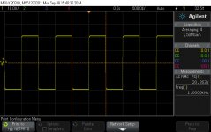
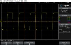
So bear in mind the effect on components of hammering a design with a squarewave test at 10 KHz or around.
richy
So bear in mind the effect on components of hammering a design with a squarewave test at 10 KHz or around.
richy
The cathode resistors are a very high quality ceramic encapsulated wirewound type.
I am interested in the plate current behaviour. Starting at 80mA after the amp has heated up for roughly one hour this goes down to 70-75mA per tube. This is a gradual change, and all the voltages on the tubes are stable with no signs of oscillations on a scope.
Is this normal?
I am interested in the plate current behaviour. Starting at 80mA after the amp has heated up for roughly one hour this goes down to 70-75mA per tube. This is a gradual change, and all the voltages on the tubes are stable with no signs of oscillations on a scope.
Is this normal?
Just a hint:- Sim scenario when I built a sextet using plain glass zircon getter 6550B's. Check heater volts drift as mains transformer windings heat up. Anything getting hot on this front ?
These 6550B bottles look quite boring but are quite robust, but emission is very heater volts sensitive. Generally I run on the high side, these types anywhere between 6.4-6.6V.
richy
These 6550B bottles look quite boring but are quite robust, but emission is very heater volts sensitive. Generally I run on the high side, these types anywhere between 6.4-6.6V.
richy
Rich, good point. I never thought about the heater voltage. Everything in the amp is regulated, except for the KT120 heaters I shall investigate!
Looks like I'm headed in the same direction...
I just completed one channel of a PP KT88 amp powered via pair of Tom Christiansen's excellent 21st century Maida regulators - one for the 6AN8 input stage and a second for the KT88's - my transformers are pulls from an 80's vintage amp and are rated for 115vac.
I am in the process of adding bias and heater regulators with a note to self... "if you regulate one supply, you should regulate all supplies..."
Now that I have the added complexity of regulation, I need to find a way to monitor the bias voltage and shut down the amp if the bias regulator should somehow fail.
It will be interesting to see if going down the regulation alley will result in better sound and longer tube life.
Rich - the KT120 bias supply drifts in response to the temperature. The negative regulator uses a MOSFET CCS developing 65V across a resistor - the temperature inside the amp after prolonged operation rises from about 25C ambient to about 50C (measured with a thermocouple and the box closed) with full output after 1 hour. This drifts VGS on the mosfet and off we go .. 2V bias drift. Fixed with a small value NTC thermistor. Now everything is rock solid. I now realise just how much you need to think about in an amp this size / output, most of it I had covered off but thermal management is a real issue. All of the components inside are high grade, 105C caps, teflon wiring, double insulated B+ etc with a lot of ventilation slots but if I did it again I would be een more careful around this.
Jaimo - I have monitored the bias voltage indirectly, by monitoring cathode current. This captures more types of failure, e.g. direct shorts inside the tube. There is also the fact that monitoring something which needs to stay below a value (e.g. cathode current across a shunt) is easier in circuit terms thatn monitoring something that needs to stay above a value (e.g. bias voltage) because of startup conditions in the amp.
I have used the 'Modern Maida' in this amp, a pair (one per leg of the PPP output stage) because of the high current requirement, the continuous current draw into the output stages is about 500V @ 450mA RMS at full output, with pusles to more than twice that value. I've used very big MOSFETS (IKTK22N100L) and maybe one could have lived with this but I used a pair of regulators to be on the safe side. The B+ rails have zero modulation at full output, so I feed one of them straight into the driver board which has decoupling in it anyway. I have a view that any decent amp should have clean 'stiff' power rails. I have to buildthe second amp to find out if all that heating and complexity has been worth it.
The negative regulator is a version of the 'Swensson' design. I found this to have as good performance as the Maida but to be oscillation prone versus varying loads, fine for a pre-amp or a bias supply but no good for a power stage. If I did this again I would just use another Maida - you don't actually need a negative regulator because the bias comes from a complete separate winding on the transformer not a tap so a positive regulator is fine.
I regulated the heaters for the input stages because this was the only way to get rid of some residual 50Hz noise even in my breadboard version.
I did not regulate the KT120 heaters because that would have needed a SMPS (8A total heater current for 4xKT120) and I do not understand them well. I also achieved a silent amp in noise terms without doing this so why bother?
Now, I have just 'treated' myself to a Lamba GENH600-1.3 bench PSU - 600V @ 1.3A. I'd love to know what's inside that! My next project is a big single ended amp with 13E1s...
Approp regulators, for nearly 40 yrs, I use a simple two stage foldback with a pnp ZTX pass tranny and a mosfet in the feedback correction giving a ripple rej way down to SS 790xx devices; absolutely no issues, as it becomes easy to implement x bit voltage selection. It seems you are running the uncorrected mosfet in the knee zone, vulnerable to an uncorrected Rds res,which will easily double under a chassis hotspot.
Agree no point, power heater regulation, as no-one ever did it in the past.
richy
Agree no point, power heater regulation, as no-one ever did it in the past.
richy
Last edited:
- Status
- This old topic is closed. If you want to reopen this topic, contact a moderator using the "Report Post" button.
- Home
- Amplifiers
- Tubes / Valves
- KT88 Parallel Push Pull