I recently decided to take a closer look at the Dared MP-2a3c innards and see how it's made. At first sight it looks like simple PCB that is well laid out. I see some Nichicon caps in the power supply and some cheap coupling caps that need to be replaced. Internal signal wires also look cheap and cheesy.
The four black coupling caps are .47k, 2 of them 400v and two 630v. I looked at Auricaps and Solen for replacement. My concern is that Auricaps are 600v rating (the next one is 1500v), and I wonder if they could substitute the 630v ones. I could always use Solen caps for the 630v pair...
Also is there anything else I should or could address while dissecting this amp?
An externally hosted image should be here but it was not working when we last tested it.
An externally hosted image should be here but it was not working when we last tested it.
An externally hosted image should be here but it was not working when we last tested it.
In the third pic you can see OMRON H3Y-2 5 sec timer, which is used as some sort of "soft starter" which is not. I would imagine it simply allows heater filaments to get to temperature before kicking in the current for the rest of the electronics. Its operation produces loud "pop". I wonder if it could be replace with suitable real soft start pcb assembly.
I see a pair of pig-tail fuses soldered to the PCB. I would remove these and run wires to a pair of through chassis fuse holders mounted somewhere for convenience sake. Perhaps on the rear apron if space allows, or even on the top side. This makes replacing them very easy should you ever have to.Also is there anything else I should or could address while dissecting this amp?
600 volt caps for 630V, virtually the same....so no problem-o. The actual in circuit voltage is probably less anyway. But the brand name units may well be much bigger and more difficult to mount.
I'm not prepared to say what, if anything, is better since I don't know for sure just what it's doing. But I will say there is nothing wrong with relays. But if it makes a loud pop, then perhaps a simple timer and solid state relay might work better. Or maybe a capacitor across the contacts.- is there anything better than this semi-mechanical timer?
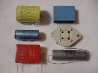
I am surprised that an Auricap is so small. But then I never buy them. I'm not convinced they're worth the price. I'm too old school and have many hundreds of capacitors stashed away. The caps in your picture look pretty small to begin with using the 4-pin socket as a size reference. Most likely made in Asia. Below are some various .47/600v units except the first one. ICC, Rifa, ERO/Roderstein, socket, Wima & Sprague Vitamin Q.
Attachments
Did the upgrade. Auricap 600v caps were significantly larger and some fitment issues arose. Everything is back together and the amp sounds really good. The stock "audiophile" caps were tossed - I had to cut their leads and solder Auricap wires to them (wires were too thick for pcb board).
An externally hosted image should be here but it was not working when we last tested it.
I replaced the coupling caps with Auricaps. As you can see they are significantly larger than the stock ones, I should've probably used the 450V instead of 600V...But esthetics aside everything sounds great.
I took a closer look at the PCB. I don't have the schematics and I am no expert in electronics but...The 2a3c filament circuit is currently powered by 2.5 V ac current which may cause some audible 120 Hz hum. On the PCB we can see the provision for DC circuitry with a rectifier and filtering cap for each tube. I circled it red on the top of the pic. The markings on the board are Q2 and Q3 for rectifiers and C20 and C21 for caps. It is somewhat simplistic but I wonder if it would work.
On the bottom of the pic I circled two bypass (probably) 100mf caps and two empty spaces for similar caps - one for each 12a..7 tube. Some dared amps I looked at have no caps there at all. It leaves some space to experiment I guess, what cap does what to the sound.
I would ask experts to chime in. Again, my knowledge of electronic circuits is on 101 level so please forgive me if my comments look silly...
Last edited:
- Status
- This old topic is closed. If you want to reopen this topic, contact a moderator using the "Report Post" button.
- Home
- Amplifiers
- Tubes / Valves
- Dared MP-2a3c mods