Hi all,
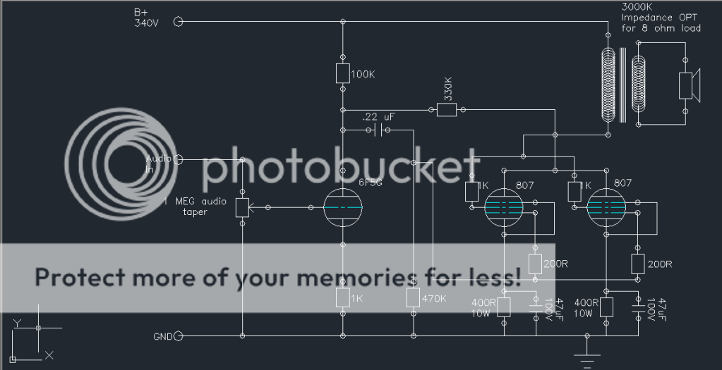
I'm about to start my second amp project, and this time my goal is to use up some tubes I have in my parts bin. The tubes I'm going with are a 6F5 and two 807's. My main idea here was to modify the RH 807 SE schematic to use two 807 tubes in parallel for the output stage. Take a look at my modified schematic and let me know if you see any major problems. This is my first try at my own circuit, so it's very possible that I made some errors here. The first picture is my design, and the second one is the RH 807 SE circuit.
Let me know what you think,
-Matt
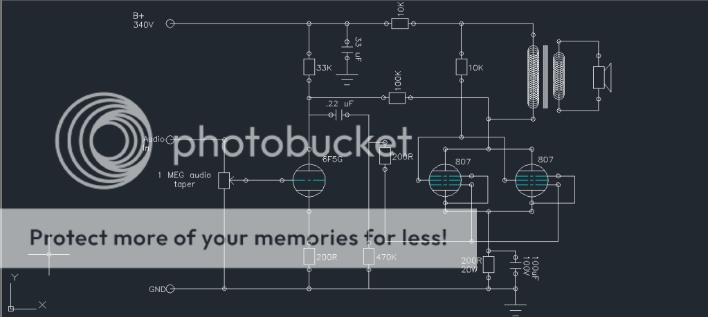
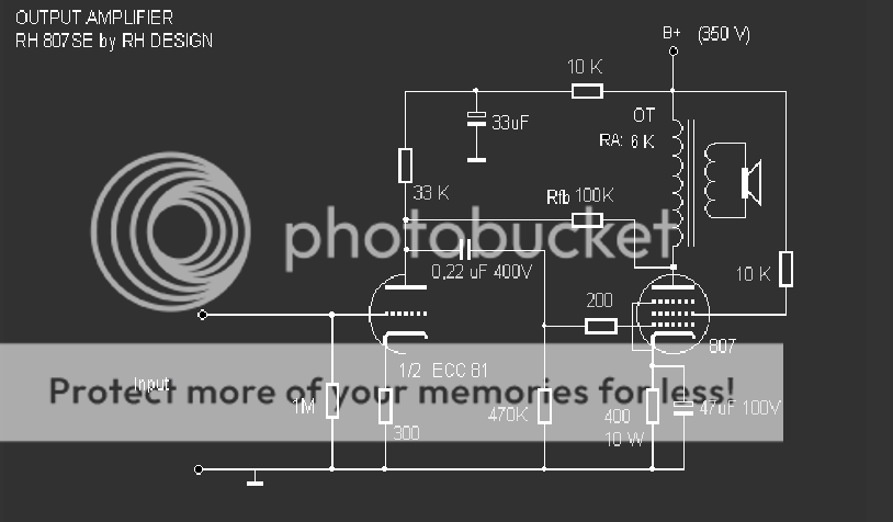
Have you noticed that 6F5G is very different sort of tube than ECC81 used in RH 807 SE. You have biased this tube to too high anode current, or at least to untypically high, some 3 mA. You can get more gain and less distortion if the anode resistor is 100 k and cathode resistor 1 k.
This modification requires that you modify the 100k feedback resistor to bigger size.
Try something between 220k to 470k.
The output transformer should now be 3k instead of 6k as in RH 807 SE.
This modification requires that you modify the 100k feedback resistor to bigger size.
Try something between 220k to 470k.
The output transformer should now be 3k instead of 6k as in RH 807 SE.

Seperate grid resistors as well, right on the socket. The 10kohm in the supply is surely not intended to go to the OPT, but VAS only. Is that a so called 'Shade-feedback'? The supply will need more than 33uF, but I'm sure you know that. Aren't these tubes happier at a higher b+? With only 340V one'd think this is a class-A2 design and using low impedance OPT? (Of course it's not b/c the VAS cannot drive the output tubes in A2). What OPT are you using?
@SemperFi
I'm actually not quite sure what that 10K resistor on the B+ is doing there, should I just get rid of it? To get this schematic, I basically took the RH807SE schematic and added parallel 807 tubes to try and get more power out of it, I also chose the 6F5 because it's a similar triode to a 12AX7 section, and I have a particularly sexy looking 6F5 in my parts box. I am planning on going with a 3Kohm impedance OPT, but I haven't selected the actual model yet. As for the B+ voltage, I can get it as high as 400 or more depending on what I do with my power filter stage. I'm using a 5U4 rectifier and an RC-LC-RC filter. Right now, the PSU design software says that my B+ should be around 340 once the transients die out. However, the loaded output voltage of my power transformer is 440V before the filter section. I actually worked to get it lower since the max plate voltage of the 6F5 tube is 300. Is there a way I can raise the B+ for the 807 tubes and still apply a lower voltage to the 6F5? As for grid resistors, I was thinking 50ohms, is this valve within reason? This is the first time I've tried to come up with my own tube circuit, so I'm still trying to figure out how to correctly pick things like plate and grid resistors.
I'm actually not quite sure what that 10K resistor on the B+ is doing there, should I just get rid of it? To get this schematic, I basically took the RH807SE schematic and added parallel 807 tubes to try and get more power out of it, I also chose the 6F5 because it's a similar triode to a 12AX7 section, and I have a particularly sexy looking 6F5 in my parts box. I am planning on going with a 3Kohm impedance OPT, but I haven't selected the actual model yet. As for the B+ voltage, I can get it as high as 400 or more depending on what I do with my power filter stage. I'm using a 5U4 rectifier and an RC-LC-RC filter. Right now, the PSU design software says that my B+ should be around 340 once the transients die out. However, the loaded output voltage of my power transformer is 440V before the filter section. I actually worked to get it lower since the max plate voltage of the 6F5 tube is 300. Is there a way I can raise the B+ for the 807 tubes and still apply a lower voltage to the 6F5? As for grid resistors, I was thinking 50ohms, is this valve within reason? This is the first time I've tried to come up with my own tube circuit, so I'm still trying to figure out how to correctly pick things like plate and grid resistors.
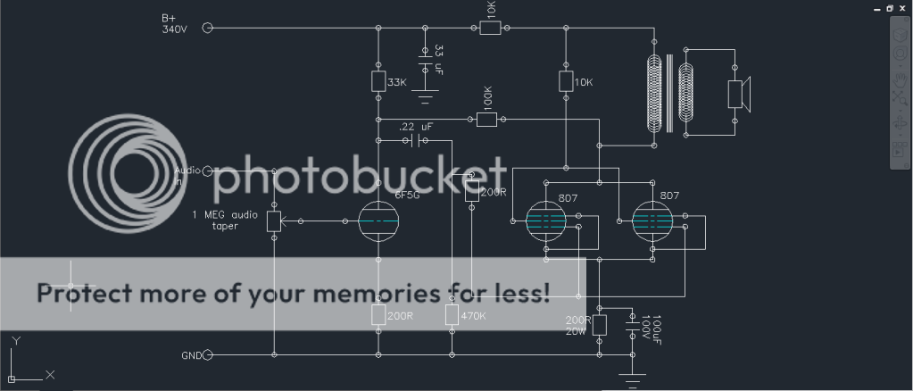
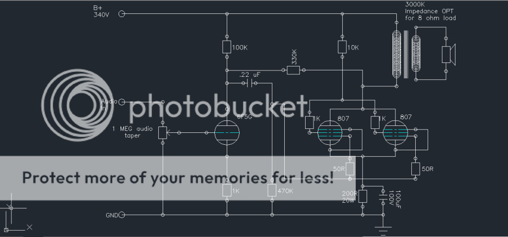
Here is the most recent revision of my schematic, am I getting close?
An externally hosted image should be here but it was not working when we last tested it.
Here are some power supply schematics and curves from the PSU designer software. Right now, I have the 340V supply indicated in the schematic. This is what that power supply layout looks like.
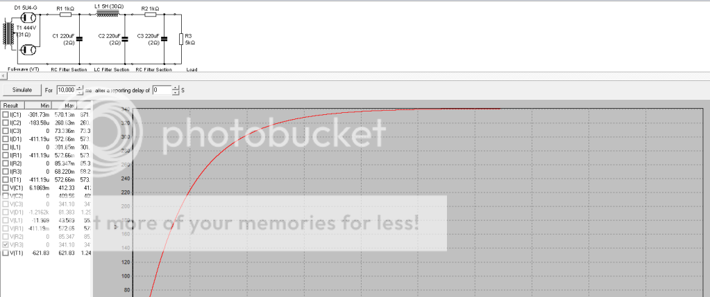
SemperFi suggested that a higher voltage may work better. By adjusting the resistors in the filter stages I can get up to around 440V out of the PSU. This next schematic shows the power supply configuration for 425V
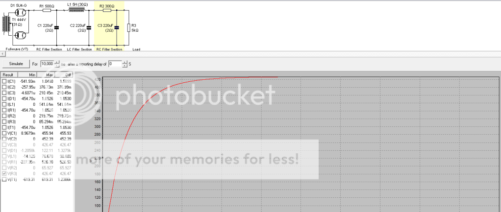
SemperFi suggested that a higher voltage may work better. By adjusting the resistors in the filter stages I can get up to around 440V out of the PSU. This next schematic shows the power supply configuration for 425V
Youre getting there") the 10k forms a filter together with the 33uF cap for the input tube. It is intended to go in series with the input tube's supply and decouples that (rather sensitive) stage from power supply variations.
the 10k forms a filter together with the 33uF cap for the input tube. It is intended to go in series with the input tube's supply and decouples that (rather sensitive) stage from power supply variations.
The 10k going to the screen needs decoupling as well. 10k is a bit high, but playing safe for your first build is ok. Can always be changed later. Decouple with a 10uF (film cap if you feel like going higher-endish).
Edit: that resistor in series with the input tube, the 10k, can be increased if you need to lower the voltage for that stage. It will drop the voltage for you so you get the voltage you need. Ohms law.
the 10k forms a filter together with the 33uF cap for the input tube. It is intended to go in series with the input tube's supply and decouples that (rather sensitive) stage from power supply variations. The 10k going to the screen needs decoupling as well. 10k is a bit high, but playing safe for your first build is ok. Can always be changed later. Decouple with a 10uF (film cap if you feel like going higher-endish).
Edit: that resistor in series with the input tube, the 10k, can be increased if you need to lower the voltage for that stage. It will drop the voltage for you so you get the voltage you need. Ohms law.
Last edited:
Youre getting there
The 10k going to the screen needs decoupling as well. 10k is a bit high, but playing safe for your first build is ok. Can always be changed later. Decouple with a 10uF (film cap if you feel like going higher-endish).
OK SemperFi, thanks a bunch for the info, now I'll have to go back and add back in some of the stuff that I just got rid of. I changed that single 10K screen resistor to a 1K on each individual screen, I'll try adding decoupling caps at each of those junctions.
-Matt
Umm. The last schem shows triode coupled 807s. If so, do not decouple!!!
What, exactly does that mean? I changed the connection point of the screen mainly to make the diagram a little cleaner. Did I change the circuit fundamentally by doing that?
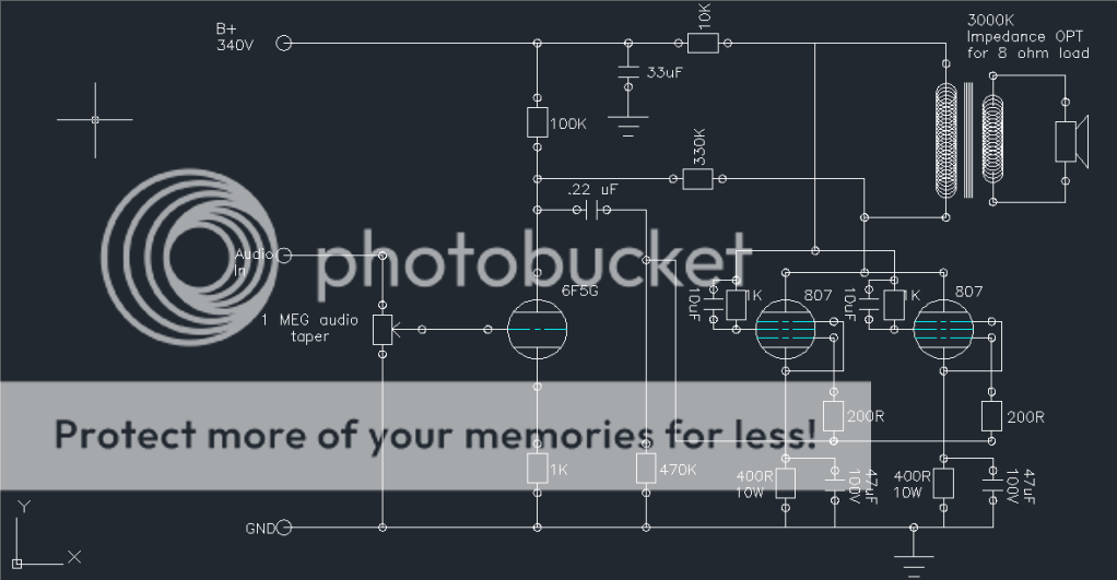
here is the schematic with the decoupling caps included, and the connection changed back to the original location. Let me know if this is more correct.
An externally hosted image should be here but it was not working when we last tested it.
What, exactly does that mean? I changed the connection point of the screen mainly to make the diagram a little cleaner. Did I change the circuit fundamentally by doing that?
here is the schematic with the decoupling caps included, and the connection changed back to the original location. Let me know if this is more correct.
The B+ supply seems incorrect now. As shown the 10k resistor will reduce the voltage to the 807 tubes a lot.
Look carefully at the RH design and how the B+ is connected. The 10k and 33uF reduces noise on the input tube.
Last edited:
OK, I see what you mean about the B+ connection, that should be fixed now. @SemperFi, yes, I am well aware of the dangers of dealing with high voltage. This is my second amp build, but the first time that I am trying to come up with my own circuit. So, here it is, revision 6 of the 807PSE schematic.

For the RH type circuit, the driver tubes need to be a tube with high transconductance, eg 12AT7. I do not know about the 6F5, but if you say it's like a 12AX7, then it is not suitable.
The 6F5 also has limited current handling, the current may not be enough to overcome the Miller capacitance of two output tubes. The high frequency response may be compromised.
The 6F5 also has limited current handling, the current may not be enough to overcome the Miller capacitance of two output tubes. The high frequency response may be compromised.
Last edited:
For the RH type circuit, the driver tubes need to be a tube with high transconductance, eg 12AT7. I do not know about the 6F5, but if you say it's like a 12AX7, then it is not suitable.
The 6F5 also has limited current handling, the current may not be enough to overcome the Miller capacitance of two output tubes. The high frequency response may be compromised.
Oh, well that kind of throws a wrench into my plans. What type of tube would you suggest? The reason I wanted to use the 6F5 was because it was an octal base with a G style envelope. I want to try to use all octal tubes for this amp, mostly for aesthetic reasons. Are there any similar triodes to the the ECC81 that are in a single triode package with an octal base?
- Status
- This old topic is closed. If you want to reopen this topic, contact a moderator using the "Report Post" button.
- Home
- Amplifiers
- Tubes / Valves
- Paralell SE 807 Amp design