Hey All,
I found a Dynaco SCA35 chassis on eBay, cheap. I also found a Sansui AU-70 for parts including all the transformers. They both used EL84 outputs and Sansui transformers were made by Tango, so I thought, this will be easy.
When I took a closer look at the Sansui schematic I found a really different way of wiring the outputs and the OPT. First off it is not an ultralinear transformer. They introduce B+1 (413v) to the center tap of the OPT primary. This resuslts in 410 volts at the plate. Then they introduce B+2 at the middle grid of the EL84. This is reminiscent of what Eli told me was called "Full pentode mode."
Then, there doesn't seem to be a cathode resistor. The cathodes are connected cross coupled to the end taps of the opt transformer secondary. Between these end taps are a ground, a 4 ohm tap and a 16 ohm tap.
I have a few questions regarding this schematic, if anyone is familiar with it. The first question is do I need to follow it to achieve the 25 watt output and the sonic quality of the transformer? Second, Since the Sansui has fixed bias with pots for each EL84 is it possible a cathode resistor is unnecessary? By connecting the end taps of the OPT secondary to the cathodes is this a cross coupled local feedback circuit? And lastly, without a cathode resistor What do you measure to adjust the bias? Negative voltage from grid to ground?
Last edited:
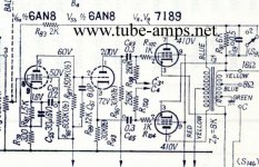
Notice that the 7189 grid resistors are connected to C3 and C4, not ground. C is the notation used for negative grid supplies. The circuit uses fixed bias.
As for 25 W. from a PP pair of 7189s, "No way Jose!". Using the tubes at the abs. max. of 13.2 W. of plate dissipation each yields a total of 26.4 W. Theory tells us that the max. possible efficiency for pure Class "B" is Π/4. So, 20.7 W. is the theoretical limit. Class "AB" operation, along with other real world considerations, brings you down to at best 17 W. Inflated claims have, and continue to, plague us.
The O/P trafos may be rated for 25 W. That provides the magnetic headroom needed to cope with a GNFB low freq. error correction signal.
No, not necessarly. The sonic quality of the transformer is determined more by it's design and build quality. And power out is a function of power in. However 25 watts from a pair of 7189's is unrealistic.do I need to follow it to achieve the 25 watt output and the sonic quality of the transformer?
CorrectSince the Sansui has fixed bias with pots for each EL84 is it possible a cathode resistor is unnecessary?
Yes it is. The cross coupling is a function of the winding direction (phasing) of the transformer. This is a practice used by more then one manufacturer to reduce distortion generated in the output stage itself.By connecting the end taps of the OPT secondary to the cathodes is this a cross coupled local feedback circuit?
Measuring the negative grid voltage will give you the bias level. Remember bias is the voltage that determins tube idle current. If you measure, and then know, the resistance of the transformer secondary between the ends and 4 ohm ground, then measuring the positive voltage at the cathode will let you determine tube current with simple ohms law. I=E÷RWhat do you measure to adjust the bias? Negative voltage from grid to ground?
Thanks All,
Dyanco rates the sca35 at 17.5 watts per channel. I guess Dynaco is not inflating the spec as Sansui did. Sansui and Tango worked closely together in designing and building these transformers so I think I'll keep the cross coupled feedback. So in effect they're using the resistance between the end taps and ground as a cathode resistor, or at least I can use it to measure the idle current.
And they are using the end taps to make the local NFB applied even? If I were to move the ground to the end tap instead of the green wire, which we are assuming is a 4ohm tap, would it still function in the feedback loop? In that way I could recover the 4 ohm output? Also, If I were to insert a small resistor, say 1 ohm, between the cathodes and the secondary taps it would decrease the feedback slightly but give me an easy place to measure idle current wouldn't it?
But then there is still the question of applying the B+2 to the middle grid. Is that necessary? Why do they do that?
Kevin
That's not the main objective. The objective is the signal feedback. The resistance is just there and one is stuck with it. But you can use it for measurment none the less.So in effect they're using the resistance between the end taps and ground as a cathode resistor
Yes, it's balanced feedback.And they are using the end taps to make the local NFB applied even?
NO! you would unbalance it . Leave it as is.If I were to move the ground to the end tap instead of the green wire, which we are assuming is a 4ohm tap, would it still function in the feedback loop?
You haven't lost it. It's still useable, only the opposite end is at ground.In that way I could recover the 4 ohm output?
Yes you could do that. The amount of decrease in feedback is miniscule with a 1 ohm resistor.If I were to insert a small resistor, say 1 ohm, between the cathodes and the secondary taps it would decrease the feedback slightly but give me an easy place to measure idle current wouldn't it?
It's very necessary. Without screen grid voltage the tube won't function.But then there is still the question of applying the B+2 to the middle grid. Is that necessary? Why do they do that?
One last question? The 7199 is awfully expensive. I've seen, with minor modification, 6U8A, 6GH8A or 6AN8A can be substituted. Does anyone know which is the best to use? Or is it best to bite the bullet and buy 7199's. I noticed Jim Mcshane has a couple choices. for this type of tube is there a superior manufacturer? From what I've gathered Sylvania's are better than RCA's but beyond that I have no idea.
Try 6F1P, it is greatly underpriced.
Per the data sheet, the 6Ф1П (6f1p) looks OK. Any hints as to the "best vintage"?
Guys, how does the 6F1P compare sonically to the 7199 or the 6AN8? From my research Joe Curcio has tested the 6GH8A and 6U8A and said they produce much more distortion than either the 7199 or the 6AN8.
Hey, This might be a stupid question? But is there a double triode or a triode and pentode that code replace this single tube?
Duh. I can answer that last one myself. Joe Curcio's upgrade driver module for the Dynaco Mark III replaces a 6AN8 front end. I've already built one and it sounded great! This should work shouldn't it? Assuming I can fit 8 Noval sockets into the space of the original SCA35 board.
Another option is to maybe convert it to a ST-35 using boards or P2P. Diytube.com design is the same except uses 12AU7 & 12AX7 instead of 7247 which is available in new production. They sell a board with all the tubes and PS on it. Dynakit.com & Audioregenisis both sell boards if needed. Audioregenisis even sells a replacement board for the SCA which is set up to use the replacement tubes you mentioned. Preamp section isn't noted to be that great in the SCA-35 so a lot have been scrapped for transformers to build ST-35 clones.
What ever you do if your power trans from the AU-70 is bad go to Dave Gillespie's EFB mod which gives you fixed bias inexpensively without the need for a bias supply off the main PS trans.
diytube.com :: View topic - Improved SCA-35/ST-35 Performance
http://www.tronola.com/A_New_Look_At_An_Old_Friend_Rev0.pdf
diytube.com :: View Forum - stereo 35
Dynaco SCA-35 Upgrade and Restoration Parts EFB
Product Catalog
Rmyauck,
I may have to change the plan here. It seems that the Sansui transformers won't fit inside the Dynaco chassis. I don't want to cobble it together. So I'm going to use a pair of Sherwood S8000 output transformers. The object here is not to build a great amp. The object is to build a nice inexpensive amp that would introduce someone new to tubes when I sell it.
A question on Pentode mode? The original Sherwood schematic specs 412 volts for the plates and 402 volts for the grid. Is it that these exact voltages are necessary? Or is it the difference between the two that is important? I'm planning to use an SCA35 power transformer, (because it fits) which has a B+ of 370. How do I determine what the grid voltage should be? I checked MJ and he doesn't seem to address pentode mode at all.
As for the preamp section. I'm going to use a pair of 6GK5 triodes with 6P15P outputs. Aping a design in the Dynaco transformer catalog for use with the 410 OPT.
The phono preamp will get new tubes and passive components and leave it at that.
Kevin
Is there anything at all wrong sound wise for sonics with PP parallel output tubes? I know it isn't liked in SE!
Here using small affordable EL84 or 6V6 types in parallel for low distortion power given the approx. primary impedance and about 20-24 W/CH which would be easy for those small 7868 output trans.
Easy to drive tubes too and SCA35 power trans might work. Will work for sure if you don't need all of the preamp.
Exact voltages for OPT don't matter (As long as you don't over voltage) and in this case running them easier with less voltage may improve sonics. Less power out of course.
Randy
Hey Guys,
I was using the 412 - 402 voltage as an example. Absolute max on the 6P15P is 330 plate and 330 grid. I'm thinking about 300 on the plate. What I need to know is what determines the relationship with the grid voltage? Here, 6P15P, 6P15P-V, 6P15P-EV I found typical is 300 plate 150 second grid. But is that for full pentode? And is that voltage to applied to the tube?
An easy way to shore up the power transformer is to use a second transformer for the heaters. Radio shack sells transformers at 12.6 and 25.2 volts in different VA's for about $12. That way all the magnetic energy for the main transformer is devoted to the high voltage. Eli taught me that.
===
I finally figured out pentode mode, I think. The voltage on grid #2 has to remain constant. While the voltage on the plate varies with the output. That's why Jim McShane puts a choke before the screen supply. I think that's why the amps I looked at all have different voltages. Its not the voltage that's important its the consistency.
As far as the driver section. I'm going to use the 6AN8. You only have to change three pin connections. And Dynaco used the 6AN8 more often than the 7199 anyway.
I got the Sansui today. Heavy little amp. Trying to decide whether I should rebuild it or pull the transformers.
Kevin
Trying to decide whether I should rebuild it or pull the transformers.
That's easy, pull!

jeff
- Status
- This old topic is closed. If you want to reopen this topic, contact a moderator using the "Report Post" button.
- Home
- Amplifiers
- Tubes / Valves
- SCA35 and AU-70