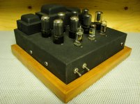
Well it's been a little over a year since I built this PPP with a couple old Magnavox. I have my UFO/RH84 running, so I can bench the big amp for a while.
For the most part it is an "Amp142or132", paraphase inverter.
Some of the changes I made was switching the inverter to 6CG7, an added 6CG7 input, choke/150u on the screens. The power supply is SS with lot's of capacitance. My OPT's are 3.9K with 3ohm and 1.5ohm taps. It has a few other values changed as well.
I liked it before I added the extra 6CG7, I still love the sound now, it's just TOO LOUD. I suppose I could bypass the extra tube, but that would leave me with an unused socket.
It's just stupid loud, I have my computer set on "1" AND I have to turn my computers preamp down -15db, just to get it to behave like a normal amp would at "1".
It is also too sensitive to noise, my sound card is next to my video card-I can hear it processing. It has guitar amp type gain.
Don't get me wrong, it's an amazing amp I'm sure lot's would like to have the power. A freight train sounds like a freight train, and transient explosions in movies will turn your pants brown if your not expecting it. I've never experienced anything like it, albiet my experience is somewhat limited compared to those here.
What I'm thinking is a complete redo.
I would love to try this amp in class A triode mode.
I understand a 6V6 in triode mode does not have much power, but considering I have four 6V6 per channel I think I can live with that.
I have two PT's for it, one is 280v, the other is 290v (132/142). I forget which I have in there.
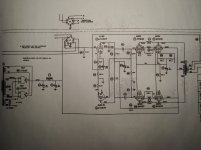
I uploaded the standard schematic of a Magnavox 132 if you want to get a general idea of the layout before I made the mods.
Generally speaking, can I apply any regular class A PP schematic to my PPP?
I'm open to suggestions and advice.
For the most part it is an "Amp142or132", paraphase inverter.
Some of the changes I made was switching the inverter to 6CG7, an added 6CG7 input, choke/150u on the screens. The power supply is SS with lot's of capacitance. My OPT's are 3.9K with 3ohm and 1.5ohm taps. It has a few other values changed as well.
I liked it before I added the extra 6CG7, I still love the sound now, it's just TOO LOUD. I suppose I could bypass the extra tube, but that would leave me with an unused socket.
It's just stupid loud, I have my computer set on "1" AND I have to turn my computers preamp down -15db, just to get it to behave like a normal amp would at "1".
It is also too sensitive to noise, my sound card is next to my video card-I can hear it processing. It has guitar amp type gain.
Don't get me wrong, it's an amazing amp I'm sure lot's would like to have the power. A freight train sounds like a freight train, and transient explosions in movies will turn your pants brown if your not expecting it. I've never experienced anything like it, albiet my experience is somewhat limited compared to those here.
What I'm thinking is a complete redo.
I would love to try this amp in class A triode mode.
I understand a 6V6 in triode mode does not have much power, but considering I have four 6V6 per channel I think I can live with that.
I have two PT's for it, one is 280v, the other is 290v (132/142). I forget which I have in there.
I uploaded the standard schematic of a Magnavox 132 if you want to get a general idea of the layout before I made the mods.
Generally speaking, can I apply any regular class A PP schematic to my PPP?
I'm open to suggestions and advice.
Attachments
Last edited:
To avoid current hogging, set up each tube of a PPP group with its own RC bias network and an individual idle current set pot. connected to a negative rail. Close matching of gm remains important, but reasonably small variations in cathode current are easily dealt with. Combination bias, as described, has LOTS going for it.
Having large reserves of power is a good thing. The only change I'd make to what you already have is the installation of voltage dividers at the I/P of each channel, to reduce sensitivity and eliminate the "hair trigger" volume control.
Having large reserves of power is a good thing. The only change I'd make to what you already have is the installation of voltage dividers at the I/P of each channel, to reduce sensitivity and eliminate the "hair trigger" volume control.
Thanks.
So I guess something around a 1k pot would be good for bias pot's so long as they can handle a couple watts? Some of the bias trimpot's I googled looked underrated. I will look some more.
So basically just hard-wire a fixed volume control at the input and be done with it.
I do have an extra hole where the second switch is located, I suppose I could stick a pot in there. (I installed the second switch in case I wanted a standby switch, kinda came to the conclusion that I don't need it. I'm on the fence.)
Have you used both sections of it i.e. one section per channel?
Trim pots / dividers will do nothing for the noise. Also , get yourself a better soundcard (preferably external)
Another idea, by glancing at your schematic: Have the 12AX7 as 1st stage, and use the 6CG7 as a nice cathode follower to drive the 6V6s. Needs some redesigning, but a cathode follower never hurt anybody.
Last edited:
T I was mainly wondering if, generally speaking I could apply most PP schematics to a PPP amp,
Only 2 differences: 1. The OPT primary impedance and 2. Drive requirements. If the power tubes operate in AB (no grid current), then the only concern is driving the input capacitance and resistance of the power tubes. Capacitance doubles. So does resistive load. I.e. if the max grid resistor allowed for a given tube is 100k, a PP driver needs to drive only 100k load, but a PPP must drive 50k.
And of course the power supply requirements for the extra tubes.
OK I think I got it.
My OPT's are 3.9K, so I should be good there.
So basically I need to make sure I have select I driver stage that can handle the extra load of PPP.
The amp is already running in PPP so I should be good, although I am at the limit for sure. (8x 6V6, 3x 6CG7)
I've got a couple of MJ's books here, been edgemecating myself to make life easier for all.
I wonder if I should take a close look at Eli Duttman's project closer.
Last edited:
Historically speaking you are both right and wrong. It DOES stand for parallel push-pull, and it WAS used in connection with the circlotron:
Circlotron History Page
Circlotron History Page
I wonder if I should take a close look at Eli Duttman's project closer.
You should tale a closer look at ALL projects!
remove the bypass cap on the 12ax7 input stage. If you need to reduce gain further, remove cathode bypass on your output tubes. you can also try a 68k resistor on the input before the grid bias resistor.
I try removing the caps as on the 12ax7 stage your signal will reduce by about 2x
the output is 50/50 but if might be easy to lift one lead and see if you like it. otherwise, a resistive pad between the input jack and the cathode bias resistor is needed.
Its better to reduce the gain of the stage than pad the signal and boost more noise floor.
P.S. Class AB has a little idle current Class B audio doesn't
Last edited:
thanck you dgta for your worthy contribution. I cannot remember the exact year but it was
around the end of the 50th when I first saw a circuit (in a "Funkschau" publication) called
paralell push pull, short PPP. It was essentially what is nowdays better known as a circlotron. As far as I know (in european countries at least) stands historically for this circuit. I do not know when and where PPP was started to be used to decribe the most common pp circuits with paralelled output tubes. The first time I stumbled over it was very recently when I tried to do a search on the "genuine" PPP circuit with little result.
I find it very disturbing that a term established more than half a century ago has now got a new meaning when at the same time the original PPP-term has become almost forgotten. I would really like to know since when and by whom PPP was first used to describe anything else than the original patented PPP-circuit?
I'm the one who called it PPP.
Any how finally got inside the amp today.
My goal was to fix up the power supply a bit. I had a stupid amount of capacitance after the choke.
I switched from 47u-6hy-1050u-100k-150u. to a more reasonable 150u-6hy-150u-100k-33u.
I also addressed how the caps were attached to the chassis. I had those stick-on nylon stand-offs, they kept letting go. Now they are attached using a plastic strap /nut and bolt.
Anyhow it brought a bit more life into the sound. I was surprised really. The treble is a little nicer now. The bass does not seem to have suffered.
So I am going to some of the suggestions. To be fair the schematic I posted earlier is quite different from what I have now, so I better get a drawing up lol.
I have a 6CG7 split going to another 6CG7 which replaced the 12AX7 paraphase inverter.
I suppose the idea of having the additional 6CG7 was to make up for the fact that the 6CG7 is a medium mu tube vs. the 12AX7 high mu.
I almost debated taking the first 6CG7 stage out and just feeding the inverter from the input.
The only concern I had with un-bypassing the cathodes is I don't want to lose any low end response. No harm in trying I suppose.
It does sound nicer though with the power supply changes I made today. Sounds a little faster. lol.
The only concern I had with un-bypassing the cathodes is I don't want to lose any low end response. No harm in trying I suppose.
Goo ahead with that. The bass will not suffer
ppp does not stand for pp with parallel output tubes. ppp is the german equivalent to a circlotron
The German speaking and English speaking HI-FI worlds did not cross-pollinate much prior to the internet age. (In North America, can't speak for the UK) The abbreviation PPP for push pull parallel has been in common usage in this part of the world for as long as I can remember..(At least 30+ years) Given that push pull parallel output stages were used here in high end radio receivers as early as the very early 1930s it seems unlikely that no one here used PPP as an abbreviation in that time frame.. Hobbyists here were building 100W Thordarson PPP designs using 6L6s in the early 1940s..
- Status
- This old topic is closed. If you want to reopen this topic, contact a moderator using the "Report Post" button.
- Home
- Amplifiers
- Tubes / Valves
- Tame the beast.