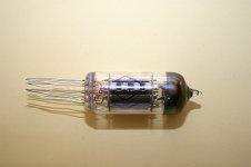
Hello to the tube people here, I'm a tube newbee and just finished my 1st tube project (aikido preamp ) and want to build a matching amp using this russian tube that my friend sold to me at 0.70usd a piece.
I have 8 of this and i want to make a low wattage amp and put it to use either SE or PP but i prefer PP. My friend told me that its a small brother of GU-29 (a double beam tetrode).
Does anyone here can help me out with some schematics. I can't find one on the internet so I brought it here. I will attached the Datasheet in russian of this rare tube. Please help me out friends...
Attachments
Hi!
Actually, it is a small sister of GU-17 tube. It was used in small UHF transmitters that hung on balloons that transmitted weather measurements on ground bases, so parameters in the datasheet were given for such disposable conditions: 6.5W per anode for 100 hours only.
I would recommend to use no more than 4W per anode so it would live longer life.
Hi!
Actually, it is a small sister of GU-17 tube. It was used in small UHF transmitters that hung on balloons that transmitted weather measurements on ground bases, so parameters in the datasheet were given for such disposable conditions: 6.5W per anode for 100 hours only.
I would recommend to use no more than 4W per anode so it would live longer life.
Thanks wavebourn for the info, i'm really expecting you to come in....so what is the ideal plate to plate impedance and bias current with a 200v supply? Can they be connected parallel just like priboy to increase anode dissipation?.
Thanks wavebourn for the info, i'm really expecting you to come in....so what is the ideal plate to plate impedance and bias current with a 200v supply? Can they be connected parallel just like priboy to increase anode dissipation?.
Yes, you can connect them in parallel, of course, to get like 8W of dissipation per tube. Speaking of load and current, try to find it using load lines that you prefer. There is plenty of information about load lines here on the forum, including step-by-step instructions.
GU-17 is biger brother for this tube (x1.5 times more power). I am not professional, but...
Try this.
ololo be prepared for troubles with encoding
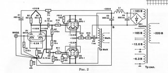
http://www.radiostation.ru/home/graphics/usil_a01.gif (audio amp)
In this schematic tube is NOT so forced like it is recommended in datasheet. And i's mode of operation is not like recommended. it makes it life longer (up to 1000 hours instead of 100).
i can't give you a comprehensive help, but if something extremely important, you can ask. but without warranty. sorry.
Try this.
ololo be prepared for troubles with encoding
http://www.radiostation.ru/home/graphics/usil_a01.gif (audio amp)
In this schematic tube is NOT so forced like it is recommended in datasheet. And i's mode of operation is not like recommended. it makes it life longer (up to 1000 hours instead of 100).
i can't give you a comprehensive help, but if something extremely important, you can ask. but without warranty. sorry.
GU-17 is biger brother for this tube (x1.5 times more power). I am not professional, but...
Try this.
ololo be prepared for troubles with encoding
http://www.radiostation.ru/home/graphics/usil_a01.gif (audio amp)
In this schematic tube is NOT so forced like it is recommended in datasheet. And i's mode of operation is not like recommended. it makes it life longer (up to 1000 hours instead of 100).
i can't give you a comprehensive help, but if something extremely important, you can ask. but without warranty. sorry.
Back from holiday.....hi nightuser....thanks for the site and schematics you shown....this will give me a better idea and basis to work on. I will try the design and what a coincidence... i also has 10 pcs of 6N16B 2 triode on hand to use as splitters. i just prepare now the OpT and supply trafo.
Ra-a in the schema is 5600ohms, Supply is 250Volts...and Pout is 5.6watt in PP mode using single tube... this is enough for me. and how about having another tube in parallel with the other.....will it be possible to reach 10watts?
I can not say anything about how to double output power as it is not present in article. and i am not professional. Author only said that it is possible to get up to 8 Watts with single GU-17.
also some translation:
in this schematics 6n16b tube works in its recommended mode. input sensivity for maximal output power is 2x0.81 V_effective (as i understand effective == RMS). Input stage gain is 20 dB. you can use balansed input or single-ended (is SE choosen, you need to connect one input (in bottom left corner) to gnd and apply signal between other (upper) input and gnd).
For your information, RH means RLoad (R Load in raussian is "R nagruzki"). KTP as i understand means Coefficient of transformation.
I can not say anything about how to double output power as it is not present in article. and i am not professional. Author only said that it is possible to get up to 8 Watts with single GU-17.
also some translation:
in this schematics 6n16b tube works in its recommended mode. input sensivity for maximal output power is 2x0.81 V_effective (as i understand effective == RMS). Input stage gain is 20 dB. you can use balansed input or single-ended (is SE choosen, you need to connect one input (in bottom left corner) to gnd and apply signal between other (upper) input and gnd).
For your information, RH means RLoad (R Load in raussian is "R nagruzki"). KTP as i understand means Coefficient of transformation.
Well i got a lot clearer idea from you...google translation somestimes i cant understand...it good you elaboarate that... i will definitly try this schema using 1 tube first for testing...thanks again.
to tubes experts here, any comments on the linked schematics if ever used two tubes in parallel?
If you decide to parallel tubes try 360 Ohm cathode resistor instead of 680 Ohm one, for the same current per tube. Result will be lower distortions on the same maximal output power. For more power, correspondingly, you will need output transformer with lower primary impedance. Also probably you will need some low ohm resistors in anode and screen grid, to stop parasitic oscillations. I saw such a tube used with an arc made of a silvered wire soldered between anodes, it oscillated such a way quite well.
Last edited:
If you decide to parallel tubes try 360 Ohm cathode resistor instead of 680 Ohm one, for the same current per tube. Result will be lower distortions on the same maximal output power. For more power, correspondingly, you will need output transformer with lower primary impedance. Also probably you will need some low ohm resistors in anode and screen grid, to stop parasitic oscillations. I saw such a tube used with an arc made of a silvered wire soldered between anodes, it oscillated such a way quite well.
Well thats a good suggestion sir wavebourn...i will take note on that and maybe a 33 to 100 ohm will be suitable enough for the anode and screen grid and planning an opt of 3.8Kohm primary...will this be good enough sir?
Last edited:
1 more important question here....lowering heater voltage will prolong tube life... is this true? and how about using SMPS regulated 5 volts like PSP power suppliesand ATX power supply.
What is the effect of using 5Vdc on filaments of low power tube and output power tubes...will it produce large distortion or will it work? anybody please?
What is the effect of using 5Vdc on filaments of low power tube and output power tubes...will it produce large distortion or will it work? anybody please?
I think 3K8 should be good.
About 5 volt... It depends on the tube. Some tubes work fine, some show weaker emission. It is less critical for indirectly cathode heated tubes.
Thanks.....in the case of this russian tubes that i have, 6n16b,6r2p,6P3s,6n1p, 6n3p and 6p18p.....also 6n8s and 6n9s....which of this tubes might work on this 5vdc filament voltage...
i know your much familiar with russian tubes...do you have any idea sir? power tubes like 6p3s and 6p18p...will their power affected?
Sorry, I did not try. May be George Tubelab knows better? He likes to explore tubes below their factory specs. I tried long time ago a single tube, 6J32P, on 5V DC filament. It worked well, and quieter.
That's a pentode i think, also have 6e6p-e and 6J11p-e. anyway, sir thanks....maybe i will have to try since i have a lot of this power supplies with real bulk current (10 amperes up) and compact packaging. I can't adjust thier output a bit higher that's why I'm asking....
Does anybody here tried to work on low voltage filament supply?...
Hi!
Actually, it is a small sister of GU-17 tube. It was used in small UHF transmitters that hung on balloons that transmitted weather measurements on ground bases, so parameters in the datasheet were given for such disposable conditions: 6.5W per anode for 100 hours only.
I would recommend to use no more than 4W per anode so it would live longer life.
Wow! When I was a kid, somebody "captured" one such soviet balloon and gave it to my dad (the town's electronics repair shop). All I remember is that it was all green parts inside, and that it was very, very difficult to dismantle!
Tubes had just arrived.....one question before designing my own PCB....with regards to the attached schematics...which is better for parallel options?
Im planning to do a priboi like ouput which is combining the two section together (1 tube) or the other way around which is splitting the two tetrodes(section 1 on top and section two down)...note that the tetrode has common cathode....which is better?
its a flexible type leads also with 6n16b submini 2 triode so putting it on pcb is needed...
Attachments
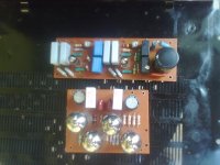
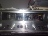
The Flexi's are in progress....finally decided to use 2 tubes 6R2P for output. Separate boards for Phase splitter and output ...housed on pioneer SX-1000 which happened to have some tube tuner so the trafo is utilized too...use quadrupler for ouput anode voltage (290V) since single 55vac tap only. Phase splitter supply and Grid is regulated at 240 volts .pix taken from low res cp camera...
Attachments
- Status
- This old topic is closed. If you want to reopen this topic, contact a moderator using the "Report Post" button.
- Home
- Amplifiers
- Tubes / Valves
- Russian 6R2P for small amp.