Are you sure you want a no feedback amplifier like this one you posted?
You can of course build the schematic you provided and substitute the 12BH7, I see no problems, calculate heater amps save that number for main transform specs, calculate the bias and total current of the tubes and choose a power transforms that has all that and respects 300V max after rectification at that total current load.
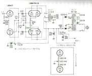
The input stage/driver stage is an adjustable long tail pair. There is 3 ways of adjusting the trim pots, 1. Equalize the current flow through of each tube, 2. Play a signal and equalize for same VRMS after the 0.047 coupling capacitors. (3. Use a THD test and minimize the THD).
Personally I am not found of push pull without feedback. I don't like also the LTP driving directly after the input either in balanced input or single ended, asking for oscillation but, if you have such an amp already and like it, I encourage you to build it.
P.s. do you know if it is chinese or Japanese writing? Looks like japan schematic!
You can of course build the schematic you provided and substitute the 12BH7, I see no problems, calculate heater amps save that number for main transform specs, calculate the bias and total current of the tubes and choose a power transforms that has all that and respects 300V max after rectification at that total current load.
The input stage/driver stage is an adjustable long tail pair. There is 3 ways of adjusting the trim pots, 1. Equalize the current flow through of each tube, 2. Play a signal and equalize for same VRMS after the 0.047 coupling capacitors. (3. Use a THD test and minimize the THD).
Personally I am not found of push pull without feedback. I don't like also the LTP driving directly after the input either in balanced input or single ended, asking for oscillation but, if you have such an amp already and like it, I encourage you to build it.
P.s. do you know if it is chinese or Japanese writing? Looks like japan schematic!
With 6N6P front end the sensitivity will be low, because gain of 6N6P is low.
And when some GNFB will be applied, the sensitivity will decrease further.
I would use 12AX7 / 6N2P-EV instead, or some other higher gain tube.
I have used soviet made 6F12P triode pentode as a voltage amplifier/cathodyne a lot and recommend that too.
What sensitivity do you want and do accept the idea of using GNFB ?
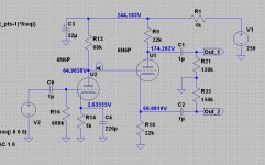
Some 11 Vrms of drive voltage is required for full power, which is about 10 W.
I think the 6N6P could give me the 11Vrms
Maybe I should use E88CC instead of the 6N6PI would use 12AX7 / 6N2P-EV instead, or some other higher gain tube.
Greets.
Tyimo
Thanks a lot for your help Artosalo!
1V is O.K. for me.Just specify what is max. input level you can accept for 10 W out ?
Is is 0,5 V, 1 V or something else ?
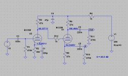
Could you show me the 6N6P version's schematic?With 6N6P the gain would be about 22...23 dB and sensitivity 0.8 Vrms.
")
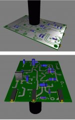
I placed some res. on top to reduce capacitance and help air circulation, I should put some holes into the pcb to help air flow.
More info: each pcb is mono, for experienced users the bias pots are placed for the side of amplifier and drill holes and access with screw driver, if someone wants to drill holes on top of the chassis or install elsewhere some bias pot you can solder small wires and route it.
I am not finished finding transformers for the power supply and a few things are not on the pcb, such as grid stoppers, bias taps, bias power supply.
I am trying to figure how the power supply could work with 250 B+ and 400V for the driver board.
The bias pot could be placed so that the adjustment is possible without opening a bottom cover, but the current of the output tubes must be measured during adjustment.
Therefore I usually place all adjustments just at the top of the pcb.
Attached is as an example a photo of my double cathodyne driver pcb (6F12P) and power supply pcb.
What sort of driver board do you plan to do, that needs 400 V ?
Therefore I usually place all adjustments just at the top of the pcb.
Attached is as an example a photo of my double cathodyne driver pcb (6F12P) and power supply pcb.
What sort of driver board do you plan to do, that needs 400 V ?
Attachments
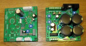
Look at the 3 black bias pots with orange color screw of my second picture. I wanted to have 2 mirror-like boards.
To follow your idea I could provide alternative bias pot placement for top of chassis access.
Yes, the driver board needs 400V which is annoying.
Your boards are nicely executed. I could use two modules, one to supply 400V/5ma, one 240V/45 mA.
To follow your idea I could provide alternative bias pot placement for top of chassis access.
Yes, the driver board needs 400V which is annoying.
Your boards are nicely executed. I could use two modules, one to supply 400V/5ma, one 240V/45 mA.
- Home
- Amplifiers
- Tubes / Valves
- 6N6P tube - focus on