ok if i were to use the c cores posted a little earlier where to start?
i did find this too:
ValveHeart_Practical Output Transformers
so if i were to figure 40W then core size is 25 to 30 sq cm for EI. How does this translate to C cores?
i did find this too:
ValveHeart_Practical Output Transformers
so if i were to figure 40W then core size is 25 to 30 sq cm for EI. How does this translate to C cores?
Take a look here, as it is also for a SS output stage; might help you to give it a start:
www.audiophonics.com/audiophonics-zeus-out-tx-75w.html
www.audiophonics.com/audiophonics-zeus-out-tx-75w.html
My advice:
Buy yourself c-cores from Alpha-Core (two cores for each transformer for a double c-core configuartion with one bobbin); 30 cm² total is good, a bit more always better.
Take wire thick enough for the DC current (3A/mm² already gives you a clue what you'd need).
Put an x number of windings on your bobbin and start experimenting.
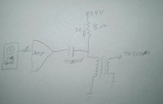
You want a 1:1 so you can wind a single coil and feed the output into the AC input of your scope; not yet necessary to wind a secondary.
As you have a scope and a generator, you can see when core saturation sets in (at what frequency and voltage level; when your generator does not output enough, no problem, core saturation is linear with frequency and AC level so you can easily calculate).
For example: put 150 windings on the coil; make an airgap between the c-core halves (start with 0.5 mm thick material between all halves), and see at what frequency and voltage the core shows saturation on your scope (you approach core saturation either by applying more voltage, or lower the frequency).
For example you see saturation at 6 Hz with 6 VRMS input with that coil.
That means you can put in 12 VRMS at 12 Hz before saturation, and so on.
When, for example, you require 40 watts at 8 ohm, you need a clean 18 VRMS at let's say 20Hz.
With your measurement you will know where you stand with your coil.
Also experiment with the airgap to see how "thin" you can go.
It takes some time, but it is the best way to do it.
When, in the end, you know how many windings are required with a given airgap to get that clean 18 VRMS at 20 Hz, see what can put on your bobbin to make the 1:1 to maximally fill your winding space (and lower DCR as much as possible).
A bifilar winding is a good approach.
In stead of the generator it will be better to build the SS output stage so that DC current is running through the coil while measuring.
Buy yourself c-cores from Alpha-Core (two cores for each transformer for a double c-core configuartion with one bobbin); 30 cm² total is good, a bit more always better.
Take wire thick enough for the DC current (3A/mm² already gives you a clue what you'd need).
Put an x number of windings on your bobbin and start experimenting.
You want a 1:1 so you can wind a single coil and feed the output into the AC input of your scope; not yet necessary to wind a secondary.
As you have a scope and a generator, you can see when core saturation sets in (at what frequency and voltage level; when your generator does not output enough, no problem, core saturation is linear with frequency and AC level so you can easily calculate).
For example: put 150 windings on the coil; make an airgap between the c-core halves (start with 0.5 mm thick material between all halves), and see at what frequency and voltage the core shows saturation on your scope (you approach core saturation either by applying more voltage, or lower the frequency).
For example you see saturation at 6 Hz with 6 VRMS input with that coil.
That means you can put in 12 VRMS at 12 Hz before saturation, and so on.
When, for example, you require 40 watts at 8 ohm, you need a clean 18 VRMS at let's say 20Hz.
With your measurement you will know where you stand with your coil.
Also experiment with the airgap to see how "thin" you can go.
It takes some time, but it is the best way to do it.
When, in the end, you know how many windings are required with a given airgap to get that clean 18 VRMS at 20 Hz, see what can put on your bobbin to make the 1:1 to maximally fill your winding space (and lower DCR as much as possible).
A bifilar winding is a good approach.
In stead of the generator it will be better to build the SS output stage so that DC current is running through the coil while measuring.
Last edited:
The CD25x50x65 is an option; a bit low in Afe but there is much winding space so you can wind quite a bit thick wire.
Please note that effective Afe is less than the geometrical dimension (for this core that is 2,5 x 5 cm = 12,5 cm²; two cores will give some 22 cm² of Afe).
Please note that effective Afe is less than the geometrical dimension (for this core that is 2,5 x 5 cm = 12,5 cm²; two cores will give some 22 cm² of Afe).
Last edited:
Give this thread a good read,
http://www.diyaudio.com/forums/planars-exotics/161485-step-up-transformer-design.html#post2088330
This is a wealth of info on transformer basics and design with lots of math and theory.
As well as how to go about checking your core for saturation per frequency and turns and voltage level.
Some of it may get confusing as I had ran into problems with my multimeter due to some highvoltage issues and are explained as I went along.
Your typical signal generator may not output enough current to cause the core to saturate.
So any good Solid state power amp should work well I was using my Aiwa cd player combo unit that is rated for about 80 watts into 6 ohms.
It does produce a 40 Vpeak (80V p-p) output swing with no load to a mild load.
Here is were I start to explain how to check for the saturation characteristics of a core,
http://www.diyaudio.com/forums/planars-exotics/161485-step-up-transformer-design-2.html#post2103369
here is some stuff you need to consider,
http://www.diyaudio.com/forums/planars-exotics/161485-step-up-transformer-design-3.html#post2121217
here Is were I presented my data,
http://www.diyaudio.com/forums/planars-exotics/161485-step-up-transformer-design-5.html#post2194027
There are few more excellent threads on transformer design, as well as some just for step down for ribbons as all of the theory is the same whether it is for step-up or step-down.
I don't have any experience on designing or working with transformers that have a D.C. Bias for S.E. but I am sure that there are others that can help with that.
I hope this helps you to get started.
jer")
http://www.diyaudio.com/forums/planars-exotics/161485-step-up-transformer-design.html#post2088330
This is a wealth of info on transformer basics and design with lots of math and theory.
As well as how to go about checking your core for saturation per frequency and turns and voltage level.
Some of it may get confusing as I had ran into problems with my multimeter due to some highvoltage issues and are explained as I went along.
Your typical signal generator may not output enough current to cause the core to saturate.
So any good Solid state power amp should work well I was using my Aiwa cd player combo unit that is rated for about 80 watts into 6 ohms.
It does produce a 40 Vpeak (80V p-p) output swing with no load to a mild load.
Here is were I start to explain how to check for the saturation characteristics of a core,
http://www.diyaudio.com/forums/planars-exotics/161485-step-up-transformer-design-2.html#post2103369
here is some stuff you need to consider,
http://www.diyaudio.com/forums/planars-exotics/161485-step-up-transformer-design-3.html#post2121217
here Is were I presented my data,
http://www.diyaudio.com/forums/planars-exotics/161485-step-up-transformer-design-5.html#post2194027
There are few more excellent threads on transformer design, as well as some just for step down for ribbons as all of the theory is the same whether it is for step-up or step-down.
I don't have any experience on designing or working with transformers that have a D.C. Bias for S.E. but I am sure that there are others that can help with that.
I hope this helps you to get started.
jer
Your typical signal generator may not output enough current to cause the core to saturate.
So any good Solid state power amp should work well I was using my Aiwa cd player combo unit that is rated for about 80 watts into 6 ohms.
It does produce a 40 Vpeak (80V p-p) output swing with no load to a mild load.
Most signal generator have a DC offset option so it is maybe possible to run some DC current through the transformer but it will be a poor simulation because 3A will not be achieved. It is best to build the amplifier sans opt for having the full DC current and AC voltage situation and then you can start making the output transformer as described in my post #29.
Last edited:
... Just remember that impedance ratio is the square root of the turns ratio. ..
Sorry, Chris, but I think you mixed up something!
Impedance transformation is winding ratio squared, not the square root of it.
Best regards!
Sorry, Chris, but I think you mixed up something!
Impedance transformation is winding ratio squared, not the square root of it.
I was thinking one thing and wrote another. Of course it has to be as you say. Thanks. I is good to correct these kinds of thinks in forums or year later some one will find the wrong answer using Google.
winding or turns ratio is equal to the square root of the impedance ratio.......
Hi Tony,
that's exactly what I said two posts before. Isn't it?
- Status
- This old topic is closed. If you want to reopen this topic, contact a moderator using the "Report Post" button.
- Home
- Amplifiers
- Tubes / Valves
- help me build an output transformer