

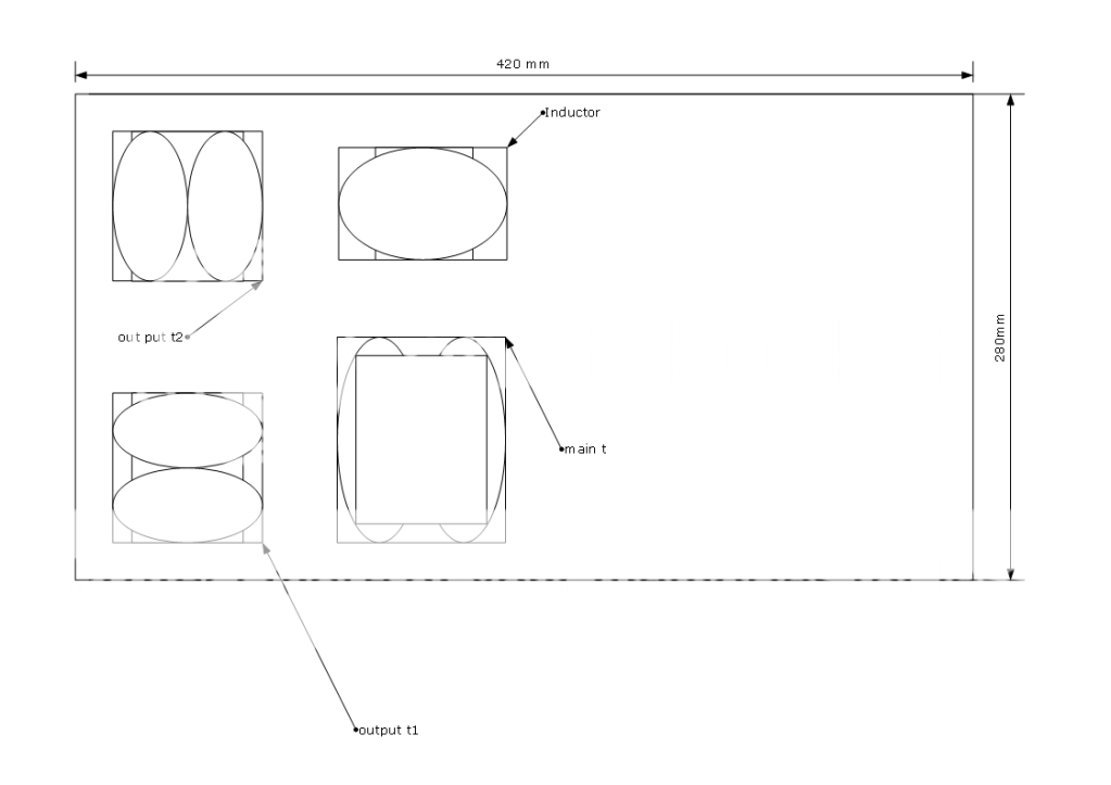
That's correct for orientation, but the point was made that the choke should be in the corner not in the center and the same with the PT; so put them over on the left edge. If you are using a rectifier tube it can probably go between the two PS transformers. The output transformers will be between your highest EMF generators and your signal tubes which will be in the space to the right. Distance is everything with the EMF so put your PS as far as possible from your signal components; that's just basic good layout practice.
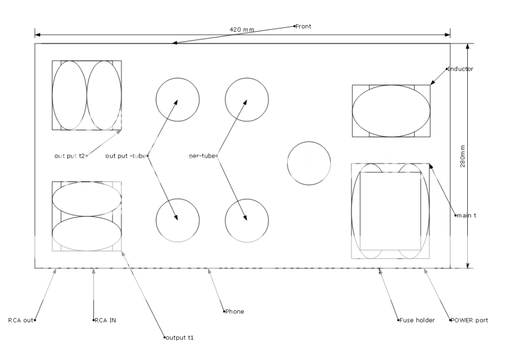
And the highest EMF generator will be the Main power transformer~
If your power supply is choke input, don't be surprised to find the choke puts out the most severe field. It can be nasty due to the amount of voltage swing and the sharp transitions each 120Hz cycle.
- Status
- This old topic is closed. If you want to reopen this topic, contact a moderator using the "Report Post" button.
- Home
- Amplifiers
- Tubes / Valves
- E-M-field problem