Could you possibly share the spice model for 6P41S and 6P9P ?
I have plenty of these tubes but not Spice models.
Also I am looking for Spice models of soviet tubes in general.
** GM70 ************************************************************
* Created on Sun Nov 13 19:04:11 EST 2011 using tube.model.finder.PaintKIT
* Traced by Kevin Kennedy and revised for LTSpice compatibility
*--------------------------------------------------
.SUBCKT GM70 1 2 3 ; P G K ;
+ PARAMS: MU=7.644 EX=1.274 KG1=1455.0 KP=135.0 KVB=24.75 VCT=0.2320
* Vp_MAX=2000.0 Ip_MAX=0.3 Vg_step=20.0
*--------------------------------------------------
E1 7 0 VALUE={V(1,3)/KP*LOG(1+EXP(KP*(1/MU+(VCT+V(2,3))/SQRT(KVB+V(1,3)*V(1,3)))))}
RE1 7 0 1E9
G1 1 3 VALUE={(PWR(V(7),EX)+PWRS(V(7),EX))/KG1}
RCP 1 3 1E9 ; TO AVOID FLOATING NODES
CCG 2 3 8p ; CATHODE-GRID
CGP 2 1 12p ; GRID=PLATE
CCP 1 3 4p ; CATHODE-PLATE
D3 5 3 DX ; FOR GRID CURRENT
RGI 2 5 2000 ; FOR GRID CURRENT
.MODEL DX D(IS=1N RS=1 CJO=10PF TT=1N)
.ENDS GM70
Perhaps this is of interest and hopefully not too far OT.
Edit: Note that I have replaced the model with one that will work properly in LTSpice and also revised CCG, CGP, CCP values to reflect the data sheet. Hopefully it works OK.. (Seems to behave more or less as I would expect in a quick run.) Note that I have removed an earlier version and replaced it with this so you should check to see if this is what you have.
I can recommend Rod Coleman's large DHT CCS based on my own experience.
Here is the data sheet I used to generate my model: http://www.mif.pg.gda.pl/homepages/frank/sheets/084/g/GM70.pdf
An alternative data sheet is here: http://www.mif.pg.gda.pl/homepages/frank/sheets/018/g/GM70.pdf
Filament power consumption is 60W (3A x 20V) and for SE operation needs to be DC for low noise.
The GM70 sounds very good.
6S19P
** 6S19P ************************************************************
* Created on Mon Nov 14 22:57:01 EST 2011 using tube.model.finder.PaintKIT
* Traced by Kevin Kennedy
*--------------------------------------------------
.SUBCKT 6S19P 1 2 3 ; P G K ;
+ PARAMS: CCG=6.5P CGP=8P CCP=2.5P RGI=2000
+ MU=2.3520 EX=1.526 KG1=2235.0 KP=19.5 KVB=1.875 VCT=0.0280
* Vp_MAX=380.0 Ip_MAX=0.15 Vg_step=20.0
*--------------------------------------------------
E1 7 0 VALUE={V(1,3)/KP*LOG(1+EXP(KP*(1/MU+(VCT+V(2,3))/SQRT(KVB+V(1,3)*V(1,3)))))}
RE1 7 0 1G
G1 1 3 VALUE={(PWR(V(7),EX)+PWRS(V(7),EX))/KG1}
RCP 1 3 1G ; TO AVOID FLOATING NODES
C1 2 3 {CCG} ; CATHODE-GRID
C2 2 1 {CGP} ; GRID=PLATE
C3 1 3 {CCP} ; CATHODE-PLATE
D3 5 3 DX ; FOR GRID CURRENT
R1 2 5 {RGI} ; FOR GRID CURRENT
.MODEL DX D(IS=1N RS=1 CJO=10PF TT=1N)
.ENDS 6S19P
Again provided without warranty, but it does seem to work OK in LTSpice. I had a little more trouble matching the curves on this one, not quite as close as I would have liked, but within a few % or better.
Here are the 6P41S and 6J9P:
I made the model for the 6P41S using "Paint_KIP.jar" from this site:
Model Paint Tools: Trace Tube Parameters over Plate Curves, Interactively
Both models suffer from g2 not accuratly depicting screen current at low current levels. I have seen the same problem with Koren models for 6V6, so this seems to be a common problem.
** 6P41S ************************************************** **********
* Created on Wed Jun 15 21:32:10 EDT 2011 using tube.model.finder.PaintKIP
* model URL:
*--------------------------------------------------
.SUBCKT PENT_6P41S 1 2 3 4 ; P G K G2
+ PARAMS: CCG=3P CGP=1.4P CCP=1.9P RGI=2000
+ MU=91.184 EX=1.3719 KG1=275.0 KG2=4500.0 KP=10.65 KVB=45.0 ; Vp_MAX=420.0 Ip_M
AX=0.256 Vg_step=1.0
*--------------------------------------------------
RE1 7 0 1MEG ; DUMMY SO NODE 7 HAS 2 CONNECTIONS
E1 7 0 VALUE= ; E1 BREAKS UP LONG EQUATION FOR G1.
+{V(4,3)/KP*LOG(1+EXP((1/MU+V(2,3)/V(4,3))*KP))}
G1 1 3 VALUE={(PWR(V(7),EX)+PWRS(V(7),EX))/KG1*ATAN(V(1,3)/KVB)}
G2 4 3 VALUE={(EXP(EX*(LOG((V(4,3)/MU)+V(2,3)))))/KG2}
RCP 1 3 1G ; FOR CONVERGENCE
C1 2 3 {CCG} ; CATHODE-GRID 1
C2 1 2 {CPG1} ; GRID 1-PLATE
C3 1 3 {CCP} ; CATHODE-PLATE
R1 2 5 {RGI} ; FOR GRID CURRENT
D3 5 3 DX ; FOR GRID CURRENT
.MODEL DX D(IS=1N RS=1 CJO=10PF TT=1N)
.ENDS
The 6J9P is a hodgepodge of bits and peices I stitched together and follows:
*-----------------------------------------------------------------------
*
* Filename: 6J9P.inc 6-14-2011
* Simulator: LTSpice
* Device type: Pentode
* Device model: 6J9P
*
* Author: Steven Parfitt
* Date: 6-14-2011
* Copyright: (C)
* Pins A Anode
* S Screen
* G Grid
* K Cathode
*
*----------------------------------------------------------------------
*
* The following parameters are not modelled:
*
* (1) Heater
*
* Please note that this model is bits and pieces taken from several sources and as such
* is provided "as is" with no warranty or other guarantee of its suitability
* for any application.
*
*
.SUBCKT 6J9P A S G K
.PARAM VA0=100
.PARAM VS0=150
.PARAM VG0=-1
.PARAM IA0=43m
.PARAM IS0=5m
.PARAM MU=72
.PARAM STEPEN=1.5
.PARAM KSA=0.1
.PARAM NORM=PWR((VS0/MU+VG0),STEPEN)
.PARAM PEREGIB=1000
.PARAM NORM2=(2*PWR(VA0,2)+VA0)/(2*PWR(VA0,2)+VA0+PEREGIB)
Bgs gs2 0 V=PWR((URAMP(V(S,K)/MU+V(G,K))),STEPEN)/(NORM)
Bn n 0 V=V(A,K)/(V(gs2)+1u)
Bat WIN 0 V=(2*PWR(V") ,2)+V)/(2*PWR(V,2)+V+PEREGIB)/(NORM2)
,2)+V)/(2*PWR(V,2)+V+PEREGIB)/(NORM2)
Banode cc 0 V=V(gs2)*V(WIN)
*
* Calculate anode current
*
Ba A K I=(IA0+IS0)*V(cc)*(1-KSA)
*
* Calculate screen current
*
Bscrn sc 0 V=V(gs2)*(1-V(WIN))
Bs S K I=(IA0+IS0)*V(sc)*(1-KSA)+KSA*((IA0+IS0)*V(cc))
*
* Grid current (approximation - does not model low va/vs)
*
Bg G K I=PWR((URAMP(V(G,K)),1.5))*50E-6+V(G,K)/30Meg
*
* Capacitances
*
Cg1 G K 13.5p
Cak A S1 1.8p
Cg1a G A 0.045p
R1 S1 K 0.01
Cs1 S1 G 1p
Cgs G S 3p
.ENDS
Both suffer from low screen current at low plate current values. This seems to be typical for pentode/tetrode models as I've seen the same problem with 6V6 and 6L6 models.
I made the model for the 6P41S using "Paint_KIP.jar" from this site:
Model Paint Tools: Trace Tube Parameters over Plate Curves, Interactively
Both models suffer from g2 not accuratly depicting screen current at low current levels. I have seen the same problem with Koren models for 6V6, so this seems to be a common problem.
** 6P41S ************************************************** **********
* Created on Wed Jun 15 21:32:10 EDT 2011 using tube.model.finder.PaintKIP
* model URL:
*--------------------------------------------------
.SUBCKT PENT_6P41S 1 2 3 4 ; P G K G2
+ PARAMS: CCG=3P CGP=1.4P CCP=1.9P RGI=2000
+ MU=91.184 EX=1.3719 KG1=275.0 KG2=4500.0 KP=10.65 KVB=45.0 ; Vp_MAX=420.0 Ip_M
AX=0.256 Vg_step=1.0
*--------------------------------------------------
RE1 7 0 1MEG ; DUMMY SO NODE 7 HAS 2 CONNECTIONS
E1 7 0 VALUE= ; E1 BREAKS UP LONG EQUATION FOR G1.
+{V(4,3)/KP*LOG(1+EXP((1/MU+V(2,3)/V(4,3))*KP))}
G1 1 3 VALUE={(PWR(V(7),EX)+PWRS(V(7),EX))/KG1*ATAN(V(1,3)/KVB)}
G2 4 3 VALUE={(EXP(EX*(LOG((V(4,3)/MU)+V(2,3)))))/KG2}
RCP 1 3 1G ; FOR CONVERGENCE
C1 2 3 {CCG} ; CATHODE-GRID 1
C2 1 2 {CPG1} ; GRID 1-PLATE
C3 1 3 {CCP} ; CATHODE-PLATE
R1 2 5 {RGI} ; FOR GRID CURRENT
D3 5 3 DX ; FOR GRID CURRENT
.MODEL DX D(IS=1N RS=1 CJO=10PF TT=1N)
.ENDS
The 6J9P is a hodgepodge of bits and peices I stitched together and follows:
*-----------------------------------------------------------------------
*
* Filename: 6J9P.inc 6-14-2011
* Simulator: LTSpice
* Device type: Pentode
* Device model: 6J9P
*
* Author: Steven Parfitt
* Date: 6-14-2011
* Copyright: (C)
* Pins A Anode
* S Screen
* G Grid
* K Cathode
*
*----------------------------------------------------------------------
*
* The following parameters are not modelled:
*
* (1) Heater
*
* Please note that this model is bits and pieces taken from several sources and as such
* is provided "as is" with no warranty or other guarantee of its suitability
* for any application.
*
*
.SUBCKT 6J9P A S G K
.PARAM VA0=100
.PARAM VS0=150
.PARAM VG0=-1
.PARAM IA0=43m
.PARAM IS0=5m
.PARAM MU=72
.PARAM STEPEN=1.5
.PARAM KSA=0.1
.PARAM NORM=PWR((VS0/MU+VG0),STEPEN)
.PARAM PEREGIB=1000
.PARAM NORM2=(2*PWR(VA0,2)+VA0)/(2*PWR(VA0,2)+VA0+PEREGIB)
Bgs gs2 0 V=PWR((URAMP(V(S,K)/MU+V(G,K))),STEPEN)/(NORM)
Bn n 0 V=V(A,K)/(V(gs2)+1u)
Bat WIN 0 V=(2*PWR(V
,2)+V)/(2*PWR(V,2)+V+PEREGIB)/(NORM2)Banode cc 0 V=V(gs2)*V(WIN)
*
* Calculate anode current
*
Ba A K I=(IA0+IS0)*V(cc)*(1-KSA)
*
* Calculate screen current
*
Bscrn sc 0 V=V(gs2)*(1-V(WIN))
Bs S K I=(IA0+IS0)*V(sc)*(1-KSA)+KSA*((IA0+IS0)*V(cc))
*
* Grid current (approximation - does not model low va/vs)
*
Bg G K I=PWR((URAMP(V(G,K)),1.5))*50E-6+V(G,K)/30Meg
*
* Capacitances
*
Cg1 G K 13.5p
Cak A S1 1.8p
Cg1a G A 0.045p
R1 S1 K 0.01
Cs1 S1 G 1p
Cgs G S 3p
.ENDS
Both suffer from low screen current at low plate current values. This seems to be typical for pentode/tetrode models as I've seen the same problem with 6V6 and 6L6 models.
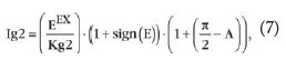
Gurskii - A Simple Tube Simulation Improvement
In the Feb 2011 issue of Audio Xpress, Dr. Gurskii presented an improvement on the Koren model for tubes with screen grid. For simulating the screen current, we can use the equation shown in the attachment.
e.g. for EF86 would be
G2 8 3 VALUE={(PWR(V(7),EX)+PWRS(V(7),EX))/KC*(2.5708-ATAN(V(1,3)/KVB))}
Hope this helps with screen current...
Jaz
Attachments
e.g. for EF86 would be
G2 8 3 VALUE={(PWR(V(7),EX)+PWRS(V(7),EX))/KC*(2.5708-ATAN(V(1,3)/KVB))}
Jaz
Jaz,
I can't find parameter <KC> in Koren's model. Can you explain ?
******************
.SUBCKT EF86 1 2 3 4 ; A G2 G1 C (Pentode)
* Philips data sheet AKA 6CF8 and 6267 Z729 EF806
* library format: LTSpice 02-Jun-2008
X1 1 2 3 4 PENTODE1 MU=34.90 EX=1.350 KG1=2648.1 KG2=4500 KP=222.06 KVB=4.7 VCT=0.00 RGI=2000 CCG=4.3p CPG1=0.6p CCP=5.1p ;
.ENDS EF86
Here is a link with two model files that have many common tubes that work with ltspice. :: View topic - Updated Tube Models
Hi Lars,
I haven't compared the two, and in fact did not know of SB's GM70 model's existence until you mentioned it.
Interesting that the curves appear so different, and I have no clue as to which is more accurate, but given Stephie's level of experience possibly her's is the more accurate model. I used paint_kit.jar to create my model and got a very good curve match the second attempt. Wondering if this is a reflection of the complexity of the model, a goof on my part or both..
I have noticed a number of differing curves for the GM70 on the web that do not seem to match well. I no longer remember where I got mine, but the predictions from those curves match actual measured performance well. (I can probably locate those curves at some point though)
I have not gotten very far in correlating the actual measured electrical performance of the GM70 in my amp with the spice model predictions, but there didn't seem to be anything that immediately caused concern. The predicted OP seems to match up reasonably well with what I have measured.
Hi Lars,
As a reality check Ug across six different GM70 samples at 980V and 120mA ranged from about -75V to -85V, at least 4 of these devices were almost exactly -80V.
Next time I am working on the amplifiers I will take some more careful measurements just to verify/refute/refine these values.
As a reality check Ug across six different GM70 samples at 980V and 120mA ranged from about -75V to -85V, at least 4 of these devices were almost exactly -80V.
Next time I am working on the amplifiers I will take some more careful measurements just to verify/refute/refine these values.
Remove .txt and try the two models. Check curves by clicking R1 resp. R6. Seems like none of them neither the datasheets are like your IRL tests.
Why not make curves from your reality test data and a Spicemodel according to that? Seems like the tubes measure quite consistent.
Why not make curves from your reality test data and a Spicemodel according to that? Seems like the tubes measure quite consistent.
Attachments
Last edited:
Jaz,
I can't find parameter <KC> in Koren's model. Can you explain ?
******************
.SUBCKT EF86 1 2 3 4 ; A G2 G1 C (Pentode)
* Philips data sheet AKA 6CF8 and 6267 Z729 EF806
* library format: LTSpice 02-Jun-2008
X1 1 2 3 4 PENTODE1 MU=34.90 EX=1.350 KG1=2648.1 KG2=4500 KP=222.06 KVB=4.7 VCT=0.00 RGI=2000 CCG=4.3p CPG1=0.6p CCP=5.1p ;
.ENDS EF86
So sorry, did not catch your post until now, it's a typo, KC should read KG2.
Jaz
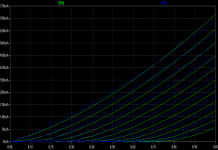
I noticed that the EL34-model from Koren which I have mostly used
is not very accurate. Ig2 is minimal and much lower than in real tube.
For example, with 250 V Ua/Ug2, the screen current is about 2.2 mA, but in Mullard specs it is some 15 mA.
I think many of us have discovered that the Koren pentode model does not work as well as his triode model, we have to tweak the parameters manually to get them to work sometimes... The best model I can find for the EL34 is from Excem, but it is a proprietary model, so must be used as is - and is very hard to adapt for other tubes...
Here is the screen current from the Excem model:
An externally hosted image should be here but it was not working when we last tested it.
Jaz
.SUBCKT 6F12PP 1 2 3 4 ; P G1 C G2 (Pentode) 28-Feb-2008
+ PARAMS: MU= 71.45 EX= 1.350 KG1= 260.8 KP=7396.95 KC= 4000
+ KVB= 17.9 VCT= 0.00 RGI= 4500k
+ CCG=6.6P CPG1=0.02P CCP=1.9P
RE1 7 0 1G
RE2 8 4 1G
E1 7 0 VALUE={V(2,4)/KP*LOG(1+EXP((1/MU+V(3,4)/V(2,4))*KP))}
G1 1 4 VALUE={(PWR(V(7),EX)+PWRS(V(7),EX))/KG1*1.57*TANH(2*V(1,4)/(KVB*3.14159))}
G2 8 4 VALUE={(PWR(V(7),EX)+PWRS(V(7),EX))/KC*(2.57-1.57*TANH(2*V(1,4)/(KVB*3.14159)))}
E2 8 2 VALUE={0}
RCP 1 4 1G ; FOR CONVERGENCE
C1 3 4 {CCG} ; CATHODE-GRID 1
C2 1 3 {CPG1} ; GRID 1-PLATE
C3 1 4 {CCP} ; CATHODE-PLATE
R1 3 5 {RGI} ; FOR GRID CURRENT
D3 5 4 DX ; FOR GRID CURRENT
.MODEL DX D(IS=1N RS=1 CJO=10PF TT=1N)
.ENDS
- Status
- This old topic is closed. If you want to reopen this topic, contact a moderator using the "Report Post" button.
- Home
- Amplifiers
- Tubes / Valves
- GM70 and Other LTSpice Tube Models