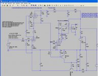
I'm still working on my 6P41S amp with a servo bias amp, but have run into a stability problem with the servo. I'm breaking the servo out as a separate issue from the 6P41S SE amp as it is my main issue and the 6P41S amp seems to be coming along fine.
My goal is to make an amp with a Mu-Stage for the input driving the 6P41S in SE mode. I will continue my observations on the 6P1S in the original thread. I am hoping to elicit discussion on servo here.
The schematics are the full amp, and the servo. The servo is sufficient for discussion (help?).
I vaguely remember stability criterion from 30 years ago in college. Regrettably I have forgotten much.
The issue is that if I increase the input capacitor (C1) above 0.047uF the system oscillates (instability). This was demonstrated in the strange plot in the original thread on the 6P41S (another SE amp)" when I changed the input cap from a 0.022 Teflon to a 0.068 PIO.
http://www.diyaudio.com/forums/tubes-valves/190797-another-se-amp-design.html
Intuitively I see that increasing C6 should make matters better rather than worse. That is, increasing it sould increase the filter capability and improve the response of the system. In reality increasing it increases lag in the system making the system less stable rather than better.
So, how do I improve the stability of the system?
Attachments
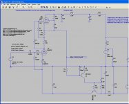
It looks like it oscillates through the bias control loop. Have you tried to slow down this loop (it should be slow anyway) like putting a cap on Q1 b-c?
What's the oscillation frequency?
jan didden
What's the oscillation frequency?
jan didden
I'm still working on my 6P41S amp with a servo bias amp
Could you possibly share the spice model for 6P41S and 6P9P ?
I have plenty of these tubes but not Spice models.
Also I am looking for Spice models of soviet tubes in general.
You need to calculate the loop gain. This is A (amp forward gain) times b (feedback circuit response). Ab, when plotted as a complex number as a function of frequency, must not loop around the (1,0) point and ideally not get too close to it either.
Artsalo, I made the model for the 6P41S using "Paint_KIP.jar" from this site:
Model Paint Tools: Trace Tube Parameters over Plate Curves, Interactively
Both models suffer from g2 not accuratly depicting screen current at low current levels. I have seen the same problem with Koren models for 6V6, so this seems to be a common problem.
** 6P41S ************************************************************
* Created on Wed Jun 15 21:32:10 EDT 2011 using tube.model.finder.PaintKIP
* model URL:
*--------------------------------------------------
.SUBCKT PENT_6P41S 1 2 3 4 ; P G K G2
+ PARAMS: CCG=3P CGP=1.4P CCP=1.9P RGI=2000
+ MU=91.184 EX=1.3719 KG1=275.0 KG2=4500.0 KP=10.65 KVB=45.0 ; Vp_MAX=420.0 Ip_M
AX=0.256 Vg_step=1.0
*--------------------------------------------------
RE1 7 0 1MEG ; DUMMY SO NODE 7 HAS 2 CONNECTIONS
E1 7 0 VALUE= ; E1 BREAKS UP LONG EQUATION FOR G1.
+{V(4,3)/KP*LOG(1+EXP((1/MU+V(2,3)/V(4,3))*KP))}
G1 1 3 VALUE={(PWR(V(7),EX)+PWRS(V(7),EX))/KG1*ATAN(V(1,3)/KVB)}
G2 4 3 VALUE={(EXP(EX*(LOG((V(4,3)/MU)+V(2,3)))))/KG2}
RCP 1 3 1G ; FOR CONVERGENCE
C1 2 3 {CCG} ; CATHODE-GRID 1
C2 1 2 {CPG1} ; GRID 1-PLATE
C3 1 3 {CCP} ; CATHODE-PLATE
R1 2 5 {RGI} ; FOR GRID CURRENT
D3 5 3 DX ; FOR GRID CURRENT
.MODEL DX D(IS=1N RS=1 CJO=10PF TT=1N)
.ENDS
The 6J9P is a hodgepodge of bits and peices I stitched together and follows:
*-----------------------------------------------------------------------
*
* Filename: 6J9P.inc 6-14-2011
* Simulator: LTSpice
* Device type: Pentode
* Device model: 6J9P
*
* Author: Steven Parfitt
* Date: 6-14-2011
* Copyright: (C)
* Pins A Anode
* S Screen
* G Grid
* K Cathode
*
*----------------------------------------------------------------------
*
* The following parameters are not modelled:
*
* (1) Heater
*
* Please note that this model is bits and pieces taken from several sources and as such
* is provided "as is" with no warranty or other guarantee of its suitability
* for any application.
*
*
.SUBCKT 6J9P A S G K
.PARAM VA0=100
.PARAM VS0=150
.PARAM VG0=-1
.PARAM IA0=43m
.PARAM IS0=5m
.PARAM MU=72
.PARAM STEPEN=1.5
.PARAM KSA=0.1
.PARAM NORM=PWR((VS0/MU+VG0),STEPEN)
.PARAM PEREGIB=1000
.PARAM NORM2=(2*PWR(VA0,2)+VA0)/(2*PWR(VA0,2)+VA0+PEREGIB)
Bgs gs2 0 V=PWR((URAMP(V(S,K)/MU+V(G,K))),STEPEN)/(NORM)
Bn n 0 V=V(A,K)/(V(gs2)+1u)
Bat WIN 0 V=(2*PWR(V👎,2)+V👎)/(2*PWR(V👎,2)+V👎+PEREGIB)/(NORM2)
Banode cc 0 V=V(gs2)*V(WIN)
*
* Calculate anode current
*
Ba A K I=(IA0+IS0)*V(cc)*(1-KSA)
*
* Calculate screen current
*
Bscrn sc 0 V=V(gs2)*(1-V(WIN))
Bs S K I=(IA0+IS0)*V(sc)*(1-KSA)+KSA*((IA0+IS0)*V(cc))
*
* Grid current (approximation - does not model low va/vs)
*
Bg G K I=PWR((URAMP(V(G,K)),1.5))*50E-6+V(G,K)/30Meg
*
* Capacitances
*
Cg1 G K 13.5p
Cak A S1 1.8p
Cg1a G A 0.045p
R1 S1 K 0.01
Cs1 S1 G 1p
Cgs G S 3p
.ENDS
Oscillation frequency is 0.25Hz with the 0.068uF cap at C1. With the 0.022uF cap it does not oscillate.
I checked PCB layout. Q1 base through 33K then wire to grid resistor of 6P41S. The bias point can be adjusted by (1) adjusting R5 (acatually a pot on pwb), or (2) adjusting R11 to change current through upper pentode. The servo works and I can set the bias on the 6P41S from 50mA to 150mA, depending on the 6J9P. They seem to vary a good bit.
Your servo circuit is basically the same thing as a series regulator for power supplies. I would look into how they are made stable. My first thought would be to remove C4 and C10 and apply C10 from collector to base of Q1.
Or remove C10 and shift 2 remaining poles further from each other.
But still, I don't see bias supply for NPN transistor base and output tube.
But still, I don't see bias supply for NPN transistor base and output tube.
Q1 is PNP and bias is supplied from the cathode of 6J9 being more negative than ground.
Maybe using a zener instead of R5 may help things as well.
Maybe using a zener instead of R5 may help things as well.
Last edited:
Hello, I recommend disconnected chain create loop,
and give signal 1000Hz input (P=.indifferently ). Chain creator instability is error diagram .
Bias 6P41C is -regulation, temporarily .
aeandm
and give signal 1000Hz input (P=.indifferently ). Chain creator instability is error diagram .
Bias 6P41C is -regulation, temporarily .
aeandm
Good ideas.
The oscillations are caused by the control loop - it's loop gain is set by the input cap, and the input source can be seen as a (low) impedance in series with the cap. The loop gain is directly proportional to that series impedance. Make C1 larger, that decreases the series impedance and that decreases the loop gain - no more oscillations. Classical.
The current position of C10 causes a lot of phase shift in the loop, exarbating the problem.
The above advice is a good start. Note that the control loop basically only needs to be a DC or very low speed loop.
You can also bang it with lots of cap at the C10 position, like 100uF or more. That'll teach it 😉
jan
Last edited:
Q1 is PNP and bias is supplied from the cathode of 6J9 being more negative than ground.
Sorry, my typo. Of course, I meant PNP. But on schematic I did not see any resistor from base to cathode, only to the anode of the preamp tube.
Anyway, 3 poles is a bit too much. I would use 2 of them with shifted from each other time constants.
The goal of the circuit is to allow me to direct couple the Mu stage output to the 6P41S.
My chain of thought was that since it is direct coupled, I can use the Mu stage to set the bias.
With the triode biased by an LED and it's anode feed from a current source it behaves like a voltage source, and it thus should be possible to control the voltage at the cathode to shift the bias to the 6P41S.
So, use the bias voltage at the 6P41S to close the loop and make it a servo.
It looks like my best approach might be to remove C10 and increase C4 to say 2200uF?
If I remove C4 and C10, what would be a good starting value for connecting from Q1b-c?
Dear diyAudio
Sorry , I slowly translate english. For me is simpler
draw diagram, now I work out a problem. I think R8
to e. Q2, and b.Q1 through additional resistor e.Q2.
R8=60mA 6P41C,additional resistor =? (-U=?)
Remove VD1 and C9 is not line element.
aeandm
Sorry , I slowly translate english. For me is simpler
draw diagram, now I work out a problem. I think R8
to e. Q2, and b.Q1 through additional resistor e.Q2.
R8=60mA 6P41C,additional resistor =? (-U=?)
Remove VD1 and C9 is not line element.
aeandm
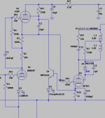
I would simplify your servo a lot, you don't need so huge OL gain; on low frequencies servo adds own distortions and instability.
Try one NPN transistor, emitter on ground, collector to screen grid of dynamic load, resistive divider from cathode of an output tube shunted by a cap to it's base.
Try one NPN transistor, emitter on ground, collector to screen grid of dynamic load, resistive divider from cathode of an output tube shunted by a cap to it's base.
Last edited:
- Status
- Not open for further replies.
- Home
- Amplifiers
- Tubes / Valves
- Closed loop stability help needed.