I will read this on my travels. I'm leaving for Guangzhou in a couple hours. Gives me something to do. If I have time I will visit the parts store in Guangzhou.
SY I read in other forums that you said on the Jolida to first do the CCS on the tail and then address the lifting of the heaters and possibly the SSRP input. I am really happy with the improvements on the CCS. Next up is the heaters. I found a transformer here are the spec (3.15-2.5-0-2.5-3.15)X2(3A)、0-12.6 (1A),0-5(2A)
I just need to make sure I have room. If not I know I can lift the existing heaters but you recommended a separate transformer if possible. As you can tell I respect your knowledge. I'm really happy with the success so far and would like to see how far I can take this amp. I bought it direct from the factory for just over $500 shipped. It's a nice learning platform.
I think the output impedance is?
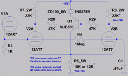
Ok tricomp I spent some of my free time looking at the formula and coming to understand it. When I first looked at it I could have been trying to read Chinese. But Now I think
Re * hfe (upper) *hfe(lower) + the 1/hoe is between 390k min to 2 meg.
Re = 20
BC549 hfe 400
MJE340 30 min to 240 max not sure how to pin that one down but that was the data on the sheet.
What does the hfe1 and hfe2 mean. I do understand the dc or ac gain but does the 1 and 2 represent?
Sorry I feel like a tortoise trying to swim with the turtles here.
I could not find the BD 139 hoe. SY I looked at the curves but I didn't understand them. But I do understand that if you use high hfe transistors it's not really important because your output-impedance is very high anyway.
I was able to source all the parts except the TL783. I will need to order that. I will experiment with the B- and the other transistors when I get it.But I will replace the BD139 with MJE340 tomorrow and replace the 1/2w trimmer with a 2 watt resistor. I think for safety reasons I must.
Ok tricomp I spent some of my free time looking at the formula and coming to understand it. When I first looked at it I could have been trying to read Chinese. But Now I think
Re * hfe (upper) *hfe(lower) + the 1/hoe is between 390k min to 2 meg.
Re = 20
BC549 hfe 400
MJE340 30 min to 240 max not sure how to pin that one down but that was the data on the sheet.
What does the hfe1 and hfe2 mean. I do understand the dc or ac gain but does the 1 and 2 represent?
Sorry I feel like a tortoise trying to swim with the turtles here.
I could not find the BD 139 hoe.
SY I looked at the curves but I didn't understand them. But I do understand that if you use high hfe transistors it's not really important because your output-impedance is very high anyway.I was able to source all the parts except the TL783. I will need to order that. I will experiment with the B- and the other transistors when I get it.But I will replace the BD139 with MJE340 tomorrow and replace the 1/2w trimmer with a 2 watt resistor. I think for safety reasons I must.
Re is the resistor value you use in the emitter lead to set the current- I think it will be bigger than 20R! hoe can be gotten from the curves- at the point where they flatten out, they'll be more or less parallel and have a tilt. The slope of that tilt is 1/hoe. The hfes are definitely going to be on the datasheets- if you use very old transistors, the datasheet might give beta instead, which is close enough for government work.
hoe can be gotten from the curves- at the point where they flatten out, they'll be more or less parallel and have a tilt. The slope of that tilt is 1/hoe. The hfes are definitely going to be on the datasheets- if you use very old transistors, the datasheet might give beta instead, which is close enough for government work.Ops I was trying verify if that was the resistance at the emitter but I only found this reference in MJ's book , He was talking about the resistance looking into the emitter and said that it was usually 20 ohm.
So I learned something. "silly me". I think the diyaudio forum is about learning and it just goes to show I have much to learn.
Unless I made another mathematical error my output impedance is between just over 2 meg and 16 meg. That's seems very good.
hfe lower BC549 =400
hfe upper MJE340 30-240
hoe for MJE340 = 150K
Re = 172 ohm
I was trying verify if that was the resistance at the emitter but I only found this reference in MJ's book , He was talking about the resistance looking into the emitter and said that it was usually 20 ohm. So I learned something. "silly me". I think the diyaudio forum is about learning and it just goes to show I have much to learn.
Unless I made another mathematical error my output impedance is between just over 2 meg and 16 meg. That's seems very good.
hfe lower BC549 =400
hfe upper MJE340 30-240
hoe for MJE340 = 150K
Re = 172 ohm
Thanks for the help
I changed the BD139 to MJE340 and tried a few resistors for Re but went back to the 200R variable. I played around and was able to get the drop on the L side to 165 on the plate resistors and 162.5 on the plate to grid difference and 171 and 167 on the right side.
I lifted my heater by 65 volts and things are sounding really nice. In fact a couple of day's ago I was typing on the computer and I walked in the living room and my wife was sitting in the sweet spot and paused the CD when she seen me. Her comment was, did you buy new tubes again? I thought about it and said no. She said it sounds like it. It sounds really nice. That is high praise coming from my wife.
I still want to try the neg supply and increase the output impedance even more, but for now it's sounds good. Thanks for the help!

Hi,
Have a question, and hoping to get some insight and guidance!
I'm modeling a 6SN7 front end gain stage for an amplifier, and it has an LTP driver for the power tubes. I have 2 models; one uses just a 15K resistor to set the cathode bias, and the other, using the CCS shown here (or a variant of it)
However....I see no difference in the distortion, gain or power over a range of input voltages from 0.25V to 2V. So the question is simply, what does (should) the CCS do for a differential pair amplifier? By the way, I should also mention that I've set the plate resistors equal for the CCS test, something I assume I can now due when both cathodes have a CCS. Otherwise, with a resistor bias, one triode uses a 33K plate resistor and the other a 39K resistor. I'm using Norman Koren's tube model library. I have the Morgan Jones book, unfortunately I cannot see in there where the exact benefits and advantages of a CCS are detailed.
Thanks for any insight you can provide - even pointing me at a good treatise on the subject would be useful.
Attachments
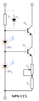
Hi, I just noticed this thread and an old outstanding question. The CCS will simply place the LTP in balance. This avoids potentially severe 2nd harmonic distortion from the imbalance caused by tube gain variance or un-compensated anode loads. So, this results in a low distortion phase splitter and amplifier.
CCS will improve the linearity and balance of LTP a lot. I see that the biggest advantage with CCS is reduced distortion.
However, my opinion is that the balance of output signals is overestimated feature.
I have noticed in practice that the best overall AC-balance is achieved when one of the anode resistors of LTP is adjustable.
Just like fixed bias voltage should be individually adjustable for output tubes.
Equal driving voltage for both output tubes is useless if the gain of the tubes are unequal.
Hi, I just noticed this thread and an old outstanding question. The CCS will simply place the LTP in balance. This avoids potentially severe 2nd harmonic distortion from the imbalance caused by tube gain variance or un-compensated anode loads. So, this results in a low distortion phase splitter and amplifier.
Hi!
Thanks for taking the time to respond on this. Since I wrote this, I have done some reading and experimenting.
My original circuit was a simple LTP resistor. It's performance was good but not stellar. After trying a few flavors of CCS, I realized as good as it sounded, it didn't. It seemed to "dry out" the sound (for lack of better words), and although I could measure just a marginal difference, I was hearing something I didn't like.
I went back to playing with LT Spice. Knowing that between the LTP and push-pull Class A amplifier I was getting high(er) levels of 3rd harmonics, I set out to tackle that by some tuning. At the end, I was able to get the 3rd harmonic to around -59dB, a 3dB improvement. But there was no 2nd harmonic to be seen. Although I don't necessarily love distortion, I also appreciate the fact that a certain amount of 2nd order brings about a pleasing sound - but I wanted just enough to be higher than the 3rd. So I "de-tuned" the LTP by making small adjustments to the anode resistors to bring up the second harmonic about 1-2dB above the third. This without affecting the level of the 3rd. Measured performance with a scope's Spec-A was fairly close to simulated (although I have yet to test thoroughly with ARTA)
It now sounds exactly what I wanted. So, perhaps this is a weird approach, but just one way to get what you want. It worked!
Gary
CCS will improve the linearity and balance of LTP a lot. I see that the biggest advantage with CCS is reduced distortion.
However, my opinion is that the balance of output signals is overestimated feature.
I have noticed in practice that the best overall AC-balance is achieved when one of the anode resistors of LTP is adjustable.
Just like fixed bias voltage should be individually adjustable for output tubes.
Equal driving voltage for both output tubes is useless if the gain of the tubes are unequal.
Agreed. I discovered by trial and error. The CCS is great where they have a place, but it wasn't for me in my application.
If you want balanced drive to the output stage, use a CCS and equal anode resistors. Other things being equal, this will minimise even-order distortion. Provided, of course, that the CCS is a good CCS with high and linear output impedance.
If you want to avoid this, then drop the CCS or use unequal resistors.
If you want to avoid this, then drop the CCS or use unequal resistors.
- Status
- This old topic is closed. If you want to reopen this topic, contact a moderator using the "Report Post" button.
- Home
- Amplifiers
- Tubes / Valves
- CCS on LTP please help