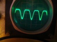
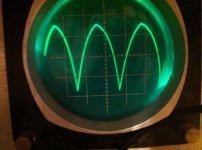
Hi all. I come with a problem. I got for free a broken oscilloscope and it's rather unknown, made in Germany in 1966 it seems, ofc it is a analog tube machine. First problem it had was with the switch-on pot, the switching part was broken so I did a direct circuit (temporary until I install a sepparate on/off switch somewhere) as the pot is still ok (pot for display intensity). After first fire-up the dot showed no problems, I attached a 100hz sine wave generated by my computer through a M-Audio Fast Track Pro soundcard so everything ok on this end. Attached the probe and sinewave came up on the tube display. The problem is that the upper part of the sinewave is "clipped", first I suspected the soundcard but luckily I have (only for a few days) a digital portable scope (Velleman) that showed a perfect sinewave, same as triangular and rectangular. But my scope seems to clip the upper part, at least distort it. I forgot to mention, my machine is a RIM Rog 7A and I can't seem to find the manual/schematics anywhere but radiomuseum where I don't have an account (I would like to ask for anyone who could send me the manual/schematics for my scope, I would very much appreciate as I don't have the means/possibilities to pay for the membership there) And they seem to be the only ones who have it online. I could only check the tube heaters, and as well I tested about 2 or 3 of the 5 E88CC's on my (now laid out on a breadboard) tube amp as it uses an equivalent for input stage/PI stage, and they seemed ok. I also discovered that the problem might have a thermal character, as when I opened the case to check the transformer voltages I discovered that the transformer has 43-45 degrees C and in about 5 minutes the shape improved a bit. After I put the cover back on I checked the temp on transformer and it only rose for 1-2 degrees. But the shapes got distorted again after 5 min or so. I also changed a 100uF/25V electrolytic as it was bloated, I think there's another one there and I got 3 big ones as well, but they seemed ok, I measured with a DMM and are in spec (I realize it isn't the most conclusive test for caps but hey, least I could do anyway. no leakage at least).
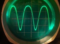
I also attached pictures with case closed and case open, you will see what I mean. (last 2 pictures are taken with open case)
I also attached pictures with case closed and case open, you will see what I mean. (last 2 pictures are taken with open case)
Attachments
Yes, I have one more 100uF/25V that I'm going to swap tonight and hopefully the 3 big ones, if I find them today somewhere... How does the scope react when one ore more tubes are out of spec? Does it still work or when they slide out of their spec it just shows garbage? I will try and source all the tubes anyway as I love the scope, as I appreciate very much vintage devices made to last! Nowadays everything is built to break down as fast as possible :/ Or you need to pay premium to have something for more than few years.
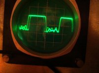
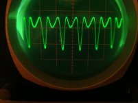
Ok, I got the schematics, and I made an easy check, I changed the EF184 between them and the problem got worse. In fact, one has 105 degrees Celsius and the other 57, and it seems that the heating problem is socket related not tube related, nevertheless seems that one tube is really screwed up. I attached a photo with a sinewave with swapped ef184
Attachments
")
I changed the 100uF/25V cap and it seems to be more sensible in a bad way, I can't seem to keep the line in place, it shakes badly now and then. I also checked the B+ rails and they are 5V lower than in the schematic. But I got different tension on the 2 100uF/25V cap, 102.5V on one and 143,1-143,9 on the other (relative to ground)
If I switch the tubes I read 87V on one and 133V on the other. These caps are on G2 of the tubes paralleled each with a 3.3k resistor.
If I switch the tubes I read 87V on one and 133V on the other. These caps are on G2 of the tubes paralleled each with a 3.3k resistor.
Last edited:
But I got different tension on the 2 100uF/25V cap, 102.5V on one and 143,1-143,9 on the other (relative to ground)
Unless the south end of that cap is floating high, 102-143 volts will definately punch a 25V cap. The voltage ratings on caps are absolute maximum they should ever see. I usually run at least 25-30% headroom above what I plan to use them at. What's the reading directly across those caps?
Doc
Winter is coming and I'm trying to fix my scope so I can work on my other projects.
I got a friend to test all of my tubes but I can't remember what he told me. I found some notes on a piece of paper in the tubes bag, one EF184 165% and the other EF184 92%. The rest of the tubes are about 67-90% each triode. I have no idea what that means but the EF184 seem way out of balance. I will buy two of those to replace.
Now on the board, I replaced some np caps, about 4 with wima mks4 0.22uF/630V because that is what I had laying around. I saw that almost all np caps in the amp are vintage Wima, mostly fluorescent yellow. I have no idea what kind they are as most of them don't have the type written on them. I found in the manual that there's some Wima Tropyfol M, metallized polyester (the 125V ones) and Wima MKB 2 (250V) and some higher voltage spec Tropyfol (400V).
As I read about the Tropyfol line many people still use salvaged ones with great success. They said they never found a leaking one so far. So I kind of trust those. Large lytics are within spec. I replaced the smaller lytics.
If you think that the new MKS4 are wrong please mention why and what to replace them with.
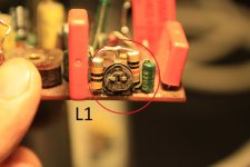
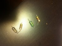
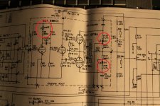
I became interested in the part that was real hot when I first tested the amp. It's about the connecting point between R28 and L3. I connected the MM clip there and when I wanted to take it off it was soldered. I made some more tests and indeed that part had molten solder with the scope on. Must have been real hot. I unsoldered the inductor and resistor from the pcb (they are connected directly one to another, not on pcb). I measured the resistor and it is within spec. I don't have and inductance meter so I cannot say anything about the state of the inductor only that it has a resistance of 3 ohms. I did the same for the other pair of R25+L2 and the resistor and inductor tested the same as the first pair. Those are mentioned as "red point" on the schematic. The only other inductor in the schematic (minus the choke) is refered to as "white point" and that is something tricky as well. I attached some pictures with the parts. The manual makes reference at the inventory of parts as 2 Hf Drosseln (inductors) - red point and 2 Hf Drosseln - white point. On the schematic there seems to be only one L1 inductor but on the board there are actually 2 inductors connected to a variable resistor as show in photo. Those inductors seem identical (the 2 L1 ones) and L2 and L3 seem identical between them. I have no idea why L1 consists of 2 identical inductors connected to a variable resistor. I also don't know the values of these inductors. The values aren't mentioned in the parts inventory nor in the schematic. They have colors on them but I couldn't find something online to decypher them. If you could help I would appreciate. I'd like to replace all 4 parts. Also I'd like to know how to operate that variable resistor with the inductors and understand it's purpose in that layout. Curious enough the R28 resistor looks like nothing I've seen before. It is all black with a white spiral on half it's body. I can only read .7K on it like the 4 from 4.7 would be under the white spiral. I'd replace the whole resistor-inductor L2 and L3 pairs as they seem like they've been under a lot of heat. What could cause that? Could it be that one of the tubes (especially the one marked 165%) drew too much current?
After I receive the new EF184 tubes I will connect everything back and resume tests.
Also it would mean a lot if I could find NOS Wima caps to replace the ugly new ones. Those oldies look incredible!
I've never seen the type of resistors on board, I'm curious to what type they are. Wirewound or carbon or...? They are 1/2W or 1/8W spec in the inventory.
Also the on-off switch is busted, that's actually a on-off potentiometer (50K). I had to bypass the on-off part of it. I couldn't find it at my electronics stores in town but I'd like to get a NOS one if possible.
Ah, one more thing. What kind of connectors are the ones on the faceplate (for the probes). I couldn't find probes with connectors like that.
I got a friend to test all of my tubes but I can't remember what he told me. I found some notes on a piece of paper in the tubes bag, one EF184 165% and the other EF184 92%. The rest of the tubes are about 67-90% each triode. I have no idea what that means but the EF184 seem way out of balance. I will buy two of those to replace.
Now on the board, I replaced some np caps, about 4 with wima mks4 0.22uF/630V because that is what I had laying around. I saw that almost all np caps in the amp are vintage Wima, mostly fluorescent yellow. I have no idea what kind they are as most of them don't have the type written on them. I found in the manual that there's some Wima Tropyfol M, metallized polyester (the 125V ones) and Wima MKB 2 (250V) and some higher voltage spec Tropyfol (400V).
As I read about the Tropyfol line many people still use salvaged ones with great success. They said they never found a leaking one so far. So I kind of trust those. Large lytics are within spec. I replaced the smaller lytics.
If you think that the new MKS4 are wrong please mention why and what to replace them with.
I became interested in the part that was real hot when I first tested the amp. It's about the connecting point between R28 and L3. I connected the MM clip there and when I wanted to take it off it was soldered. I made some more tests and indeed that part had molten solder with the scope on. Must have been real hot. I unsoldered the inductor and resistor from the pcb (they are connected directly one to another, not on pcb). I measured the resistor and it is within spec. I don't have and inductance meter so I cannot say anything about the state of the inductor only that it has a resistance of 3 ohms. I did the same for the other pair of R25+L2 and the resistor and inductor tested the same as the first pair. Those are mentioned as "red point" on the schematic. The only other inductor in the schematic (minus the choke) is refered to as "white point" and that is something tricky as well. I attached some pictures with the parts. The manual makes reference at the inventory of parts as 2 Hf Drosseln (inductors) - red point and 2 Hf Drosseln - white point. On the schematic there seems to be only one L1 inductor but on the board there are actually 2 inductors connected to a variable resistor as show in photo. Those inductors seem identical (the 2 L1 ones) and L2 and L3 seem identical between them. I have no idea why L1 consists of 2 identical inductors connected to a variable resistor. I also don't know the values of these inductors. The values aren't mentioned in the parts inventory nor in the schematic. They have colors on them but I couldn't find something online to decypher them. If you could help I would appreciate. I'd like to replace all 4 parts. Also I'd like to know how to operate that variable resistor with the inductors and understand it's purpose in that layout. Curious enough the R28 resistor looks like nothing I've seen before. It is all black with a white spiral on half it's body. I can only read .7K on it like the 4 from 4.7 would be under the white spiral. I'd replace the whole resistor-inductor L2 and L3 pairs as they seem like they've been under a lot of heat. What could cause that? Could it be that one of the tubes (especially the one marked 165%) drew too much current?
After I receive the new EF184 tubes I will connect everything back and resume tests.
Also it would mean a lot if I could find NOS Wima caps to replace the ugly new ones. Those oldies look incredible!
I've never seen the type of resistors on board, I'm curious to what type they are. Wirewound or carbon or...? They are 1/2W or 1/8W spec in the inventory.
Also the on-off switch is busted, that's actually a on-off potentiometer (50K). I had to bypass the on-off part of it. I couldn't find it at my electronics stores in town but I'd like to get a NOS one if possible.
Ah, one more thing. What kind of connectors are the ones on the faceplate (for the probes). I couldn't find probes with connectors like that.
Attachments
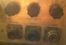
That looks like a PL259 UHF socket
See here JR6704 - -- - UHF (PL-259) MALE PLUG | CPC for an image of the plug.
a bit odd on a normal scope?.
See here JR6704 - -- - UHF (PL-259) MALE PLUG | CPC for an image of the plug.
a bit odd on a normal scope?.
Going from vague memories here - I think Tek (and possibly others) produced 'scopes with the so-called "UHF Connectors" for the inputs in the 1950's and early 1960's. I recall using the things, but don't remember model numbers, etc. You may still find compensated 10X probes with the PL-259 connector if you watch swap meets, surplus dealers, etc.That looks like a PL259 UHF socket . . . a bit odd on a normal scope?.
Dale
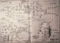
you can find the manual and schematics here: http://www.alte-messtechnik.de/archiv/ph/rim-rog7a.pdf
you can find the manual and schematics here: http://www.alte-messtechnik.de/archiv/ph/rim-rog7a.pdf
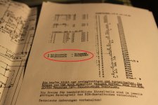
Yes, I had the manual but as I posted the pictures a few posts back the values of the inductors aren't mentioned. Only that there are 2 Hf inductors for "red point" and 2 Hf inductors for "white point". I don't know what those notations mean (red point, white point). The only lead on the values are the color stripes on the inductors.
I think that's it. I need a UHF to BNC adaptor and I can use a new set of probes!
Thank you!
No, not UHF, you need a PL-259 to BNC adaptor to fit the most common BNC probes.
The Socket is called SO-259 and the Plug is called PL-259.
5 x UHF PL-259 Male to BNC Female Adapter | eBay
If I were you I would simply replace those SO-259's with some brand new ones off eBay, the ones currently on your scope do look a bit worse for wear!
But be weary of the probes that you can get on ebay, they are great value but do have a tendency to fall apart.
http://www.ebay.com.au/itm/Chassis-...on_Coax_Cables_Connectors&hash=item3a65ca04ac
My scope has them too:

This is a 100% Transistorised Trio CS-1554 dual-trace scope with TV-signal spread spectrum functionality, that badly needs a recap, haha, I also have a Tube/transistor scope that has just recently bitten the bullet though, that one is a BWD 511
You certianly have a beautiful looking screen on that oscope, its very retro, can we get a full image of the front?
The best thing you can do for your scope is to find a second one = instant spare parts.
Last edited:
the brown resistors are of course carbon composition, I usually replace these with 1/2 watt for low voltage circuits or 1 watt for high voltage (>100v) carbon film composition.
however, in vacuum tube equipment resistors will commonly get very hot, so hot that they could burn you, and this would be considered to be normal operation.
Considering that this thread is about a vacuum tube based device, I strongly suggest that it be moved to the vacuum tube section of diyaudio.com so that it may get more exposure.
You may not want to proceed much farther without consulting with that subforum, alignment and voltages and bias is very important in an oscilloscope, especially one that is 100% tube based and you could end up knocking it into irreperable misalignment.
Also, keep magnetic objects AWAY from the cathode ray tube!!! These things don't have degauss circuits!
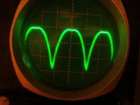
If I had to take a stab at what was the cause of the overlapping sinewave image that you had where it would rise to the peak and then fall back, I would have to say that its your vertical deflection circuit, a part there somewhere has gone awry.
Be very very careful with these units, consider discharging the HV capacitors before working on it, and if it doesn't have an internal transformer then GET an isolation transformer!! Its your own safety at risk here.
however, in vacuum tube equipment resistors will commonly get very hot, so hot that they could burn you, and this would be considered to be normal operation.
Considering that this thread is about a vacuum tube based device, I strongly suggest that it be moved to the vacuum tube section of diyaudio.com so that it may get more exposure.
You may not want to proceed much farther without consulting with that subforum, alignment and voltages and bias is very important in an oscilloscope, especially one that is 100% tube based and you could end up knocking it into irreperable misalignment.
Also, keep magnetic objects AWAY from the cathode ray tube!!! These things don't have degauss circuits!
If I had to take a stab at what was the cause of the overlapping sinewave image that you had where it would rise to the peak and then fall back, I would have to say that its your vertical deflection circuit, a part there somewhere has gone awry.
Be very very careful with these units, consider discharging the HV capacitors before working on it, and if it doesn't have an internal transformer then GET an isolation transformer!! Its your own safety at risk here.
Last edited:
I dusted off an old, 1968, Heathkit tube scope a while back. Most of the problems I had were dirty/oxidised tube sockets and dirty scratchy pots. Contact cleaner helped a lot. Check the bias voltages on each of the tube stages. How far into the circuit does your sine wave start to distort?, after the first tube, the second? It looks like one of the stages is biased wrong, leaky capacitor, bad value resistor, poor performing tube. The inductors are there to increase the gain at higher frequiencies. You should be able to short them out if you think they are bad. You will loose some HF bandwidth, but for trouble shooting it shouldn't matter too much. Can you borrow another scope to see where the sine wave starts to go bad.
- Status
- This old topic is closed. If you want to reopen this topic, contact a moderator using the "Report Post" button.
- Home
- Amplifiers
- Tubes / Valves
- got a problem with my scope, need some advice