Whichever method or meter is used to determine inductance, the result must be accompanied with the test's excitation voltage condition, and also preferably the test frequency. Jazbo's link tests at 5VAC. Using a typical 5VAC heater supply and a current meter also tests at 5VAC. Some manufacturers use a higher excitation voltage, possibly to 'enhance' the inductance value.
Many general purpose LCR meters, especially handheld modern ones, are likely to use a relatively low excitation voltage, and hence measured inductance will be substantially lower than normally reported.
The Hammond data that Ian gave earlier is a little ambiguous as to what the primary voltage value means - it could be the excitation voltage used for the inductance value test - but I have some doubt.
Yep the primary voltages in that list are the AC voltages required for rated output power - not the voltage that the primary inductance was measure at.
I tried to attach the spreadsheet to a post as it has lots of other info in it. Did'nt have any luck. Can we attach .xls files? If you want it then PM me. The file is labelled 1600.xls as it mostly covers the 1600 series trannies and was provided to me by Hammond.
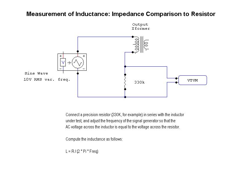
A quick search using "Measurement of Output Transformer Primary Inductance" turned up quite a few links, even a few on this forum.
Cheers,
Ian
I tried to attach the spreadsheet to a post as it has lots of other info in it. Did'nt have any luck. Can we attach .xls files? If you want it then PM me. The file is labelled 1600.xls as it mostly covers the 1600 series trannies and was provided to me by Hammond.
A quick search using "Measurement of Output Transformer Primary Inductance" turned up quite a few links, even a few on this forum.
Cheers,
Ian
Last edited:
It appears that you still do not know how to measure the OPT's, please see gingertube's post above, do you see what you are missing?
Sure , Ill do that . Thanks for the advice.
See post#4 for method
http://www.diyaudio.com/forums/tube...roper-way-measure-transformer-inductance.html
The Hammond data was not measured in this way but was provided to me in a .xls spreadsheet by Hammond.
Cheers,
Ian
Awesome Ian ! now we are getting somewhere .
Those are very high inductances , I doubt they were measured with lcr meter , i think it has been measured at full primary voltage.
I doubt they were measured with lcr meter, i think it has been measured at full primary voltage.
Primary inductance is a function of secondary inductance (times winding ratio). A very good instruction for measuring any OPT is given by M. Van der Veen (world leading expert for development of OPTs) here.
You measured low inductance with low voltage because the B-H curve (permeability) is not linear, the permeability is low when the excitation current is low. By increasing the current, there is a relatively long relatively linear section, and around the saturation the magnetic field again does not increase linearly.the question is not how to measure at this point , the question is why off the shelf OT have low inductance . Perhaps if we can get more measurements of guitar amp OTs we can make a conclusion.
Since the inductance is proportional to the relative permeability that is non-linear, the inductance itself depends on the measuring current.
It does not matter whether you measure the primary (with higher current) or the secondary (with lower current), and in most cases measuring the secondary in the order of 10s of Volts is more convenient. You can use the formule Lpri = n^2 * Lsec
Last edited:
That could be at quite low rms voltage for easy listening level, or it could be at max rated signal level at onset of output stage clipping where amp distortion is naturally a high level and your ears are complaining. Hence the generic use of a commonly available test voltage (5Vac 50/60Hz).At the voltage your amplifier should give in the load,
as you're interested in the behavior under lifelike conditions.
i think that another good thing to measure on OPT is the low frequency saturation tests, any one have procedures to do this?
There are practical problems associated with that type of testing, where a low frequency is preferred (eg. at most 50-60Hz), and the excitation level will need to be at or close to the max rated voltage depending on the transformer's designed low frequency range (ie. many 100's of volts).
Most normal signal generators with low distortion will not give that level of output voltage.
You could use a variac and a mains AC transformer with suitable secondary voltage to drive the OT. You may be lucky and have a nice sinewave at your place, but as shown in Rod's link, the mains waveform usually has a flat top, and a few % distortion.
You could emulate Rod's testing, and probe the OT primary current and watch the saturation peak increase, as well as keep an eye on rms current so you don't damage the OT. You could also record/sense an output winding voltage with a soundcard and check the frequency spectrum and %THD using software like REW5.1 and watch the %THD increase versus primary excitation voltage.
Last edited:
- Status
- This old topic is closed. If you want to reopen this topic, contact a moderator using the "Report Post" button.
- Home
- Amplifiers
- Tubes / Valves
- How to measure output transformer?