Who can upload the schematic of this monaural amplifier with a so called ultralinear output stage ?
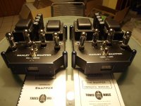
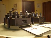
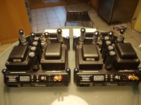
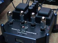
Manley Snapper
http://www.manley.com/content/product/hifi/msn/IMAGE_HIFI_1_6_SNAPPER.pdf
StereoTimes -- The Manley Snapper Monoblock Amplifiers
Manley Snapper
http://www.manley.com/content/product/hifi/msn/IMAGE_HIFI_1_6_SNAPPER.pdf
StereoTimes -- The Manley Snapper Monoblock Amplifiers
Attachments
Did you contact Manley? Looks like they will provide schematics if I read this service page correctly.
Manley Labs - GML - Service Request Form
Manley Labs - GML - Service Request Form
No. Only the German distributor without success. I will contact now Manley directly - thank you for the URL of this contact formular.Did you contact Manley? Looks like they will provide schematics if I read this service page correctly.
Manley Labs - GML - Service Request Form
I need the schematic for check the possibilities for implementing a high pass filter without additional operational amps and without any other additional silicon stuff, because this mono amp must be drive only the mid-high frequency aera in the future.
Typical active crossover networks according Sallen-Key with additional gain stages in the signal path makes the sound too harsh.
The speaker is follow: JBL250Ti
JBL - 250 Ti Service Manual auf Windows Treiber Download
JBL 250Ti
Isn't it just a matter of finding the feedback resistor to find it's value, and also the input resistor? Then use/modify those with the necessary capacitor values? Should be able to do that just looking inside?
Cool project btw, using the amp itself as the gainblock in an active filter. I've done similar with chipamps (TDA2040) for my computer speakers.
Cool project btw, using the amp itself as the gainblock in an active filter. I've done similar with chipamps (TDA2040) for my computer speakers.
I would do nothing more than add a simple first or second order HPF at the input - you should not modify the feedback loop as the amplifier may become unstable and at these power levels fried OPTs and speakers are a real possibility.
Best to do the line level X-O externally. (You can do a passive line level filter with inductors and caps as long as you know both source and load impedances or can define same at line level.)
Best to do the line level X-O externally. (You can do a passive line level filter with inductors and caps as long as you know both source and load impedances or can define same at line level.)
Best to do the line level X-O externally. (You can do a passive line level filter with inductors and caps as long as you know both source and load impedances or can define same at line level.)
I would love to find a ready source for the sizes of inductors needed to do this kind of thing.
dave
I would love to find a ready source for the sizes of inductors needed to do this kind of thing.
dave
I would too, but it's either get some outfit like Cinemag to wind them for you, or get the cores and do it yourself. Very little off the shelf.. The other issue is that impedances need to be low for this to be practical, even 600 ohms is really inconveniently high if you are not using active on the low end, mids and highs are not so bad.. The situation gets a lot better at 150 ohms and below, but here in most cases we are talking transformer coupling at the output of the line stage.
I would do nothing more than add a simple first or second order HPF at the input - you should not modify the feedback loop as the amplifier may become unstable and at these power levels fried OPTs and speakers are a real possibility.
Best to do the line level X-O externally. (You can do a passive line level filter with inductors and caps as long as you know both source and load impedances or can define same at line level.)
The modify of the feedback loop according Sallen-Key topology most amps become unstable. Probably a simple first order HPF at the input is the only solution.
But I decide the final configutaion only after exact analysing of the completely circuit topology.
Last edited:
The attachment in the response was only the Owner's Manual- go to https://static1.squarespace.com/sta...39f9f7456878ba3a275/1494463393775/SNAPPER.pdf without schematic diagram. I will try again a request. But in the meantime one of the members here have get the schematic for upload here.Did you contact Manley? Looks like they will provide schematics if I read this service page correctly.
Manley Labs - GML - Service Request Form
 Schematics of current Manley products are copyright protected.
- Status
- Not open for further replies.
- Home
- Amplifiers
- Tubes / Valves
- Schematic needed for Manley Snapper® from Manley Labs