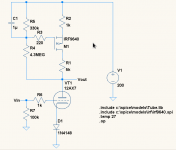
I just simulated the circuit posted by Rod Coleman in post #14. The difference is that I used a triode (12AX7 and 5751) in place of the pentode, and a 1N4148 diode instead of the LED (to get the proper bias range). I have attached the schematic.
As I predicted, performance is pretty variable depending on tube characteristics, and somewhat variable with temp. The output for a 12AX7 at 27°C is 130.095V and the tube current is 1.18mA. Running the temp up to 85°C gets us 123.996V and 1.67mA. In absolute terms it is a small amount, but given as a percentage it is a 5% change in voltage and a hefty 30% change in current.
If I replace the 1N4148 with a 507 ohm resistor (to get nearly the exact same operating conditions - in real life a common 510 ohm would be used), I get 130.182V and 1.17mA through the tube at 27°C. At 85° I get 128.771V and 1.35mA, which is a change of 1.1% and 14% respectively.
A 5751 has a mu of 70 vs 100 for the 12AX7. Gm is a bit lower as well (1200umhos vs 1600umhos). It's an admittedly wide variation, but one which works fine in most circuits. If we plug it in place of the 12AX7, put the 1N4148 back in place for bias, and set the temp back to 27° we get 121.872V and 1.77mA. Bumping the temp up to 85° results in 120.745 and 1.92mA. It seems that this circuit favors tubes with lower mu and/or gm. If I replace the diode with the same 507 ohm resistor used for the 12AX7 we get 124.835V and 1.56mA at 27° and 125.705V and 1.55mA.
Interestingly the current went down and the voltage up with increasing temp and the 5751. Nevertheless, the variation over temp with the lower mu tube and a cathode resistor is quite small. Also, variation between the 12AX7 and 5751 is less with the cathode resistor at any given temp vs diode bias.
I actually thought the temp variation would be higher than it is, while the variation with tube characteristics is about what I expected due to the fixed bias.
EDIT: I did some sims with a regular CCS. The "gyrator", which is really an operating-point compensating CCS, is indeed less sensitive to tube variation than a fixed CCS. However, both are more stable over temp with a bias resistor rather than a fixed bias diode. It's definitely an interesting variation for sure, but I will stick with pentode CCS's")
As I predicted, performance is pretty variable depending on tube characteristics, and somewhat variable with temp. The output for a 12AX7 at 27°C is 130.095V and the tube current is 1.18mA. Running the temp up to 85°C gets us 123.996V and 1.67mA. In absolute terms it is a small amount, but given as a percentage it is a 5% change in voltage and a hefty 30% change in current.
If I replace the 1N4148 with a 507 ohm resistor (to get nearly the exact same operating conditions - in real life a common 510 ohm would be used), I get 130.182V and 1.17mA through the tube at 27°C. At 85° I get 128.771V and 1.35mA, which is a change of 1.1% and 14% respectively.
A 5751 has a mu of 70 vs 100 for the 12AX7. Gm is a bit lower as well (1200umhos vs 1600umhos). It's an admittedly wide variation, but one which works fine in most circuits. If we plug it in place of the 12AX7, put the 1N4148 back in place for bias, and set the temp back to 27° we get 121.872V and 1.77mA. Bumping the temp up to 85° results in 120.745 and 1.92mA. It seems that this circuit favors tubes with lower mu and/or gm. If I replace the diode with the same 507 ohm resistor used for the 12AX7 we get 124.835V and 1.56mA at 27° and 125.705V and 1.55mA.
Interestingly the current went down and the voltage up with increasing temp and the 5751. Nevertheless, the variation over temp with the lower mu tube and a cathode resistor is quite small. Also, variation between the 12AX7 and 5751 is less with the cathode resistor at any given temp vs diode bias.
I actually thought the temp variation would be higher than it is, while the variation with tube characteristics is about what I expected due to the fixed bias.
EDIT: I did some sims with a regular CCS. The "gyrator", which is really an operating-point compensating CCS, is indeed less sensitive to tube variation than a fixed CCS. However, both are more stable over temp with a bias resistor rather than a fixed bias diode. It's definitely an interesting variation for sure, but I will stick with pentode CCS's
Attachments
Last edited:
The purpose of the gyrator circuit is to provide all the advantages of a CCS-loaded stage, while permitting the use of fixed bias.
This is not a small difference.
With an ordinary CCS load, picking a random tube will be unlikely to result in an operating point where the full output swing of the stage is available. More likely, an unusable operating point with the CCS cut-off, or excessively LOW anode voltage will appear. You already identified that a cathode resistor/cap is needed to make a practical circuit - but that almost always means an electrolytic cap! The degradation in the sound from such a component choice is not acceptable for any of my designs, nor I suspect, for many others.
With the gyrator, a workable operating point is guaranteed for any reasonable sample, and with a predictable output swing. The gyrator simply matches the current that the triode demands, at the anode voltage we choose, using the pair of resistors.
Considering that we only have to add a couple of non-critical resistors, and a non-critical cap, I'd call that a good deal.
The circuit is almost identical (but for the PNP flavour) to the Telecom line-holding circuit used in modem line interfaces in the 1980s/1990s, at least up to V.90 standard. The arrangement was certainly referred to as "Gyrator" in the UK Telecom world, so I think that Anatolij named the circuit appropriately enough.
I don't trust them implicitly either. Given decent models they are reasonably accurate. Granted, the semiconductor models we get from manufacturers aren't always the best, but temp coefficients of semiconductors simulates pretty well. While the actual voltage and currents would certainly be different in an actual circuit given the component values used, I think the general trends and percentage variations I simulated would probably be fairly close.
You don't have to bypass the resistor with a cap. You assume maximum gain is needed from the stage, which isn't usually the case. Otherwise, I pretty much agree with the points you made.
If you don't need maximum gain, it would make no sense to use a CCS load of any kind. A normal resistive-loaded stage would do equally well - but be much simpler to build.
Example: Use Ale's 6SN7 stage, 6mA anode current, 47K in the succeeding stage - as per the original post. A very standard configuration. With the Gyrator load, the gain will be about x20 or so.
With cathode bias, a cathode resistor of about 1.5K would be needed. If this is not bypassed, the effective gm of the stage is degraded from ~2.5mS to ~0.5mS, and the gain will fall near or below the x14-16 achievable with the usual 33K load resistor (bypass included).... which would also give lower output impedance.
Running without a bypass sometimes makes sense, but not with an anode load designed for high gain!
Apropos simulating these circuits - it should add to our evaluations (frequency response is especially useful). But it is not intended to substitute real design calculation, nor circuit building and evaluating.
If you don't need maximum gain, it would make no sense to use a CCS load of any kind. A normal resistive-loaded stage would do equally well - but be much simpler to build.
Example: Use Ale's 6SN7 stage, 6mA anode current, 47K in the succeeding stage - as per the original post. A very standard configuration. With the Gyrator load, the gain will be about x20 or so.
With cathode bias, a cathode resistor of about 1.5K would be needed. If this is not bypassed, the effective gm of the stage is degraded from ~2.5mS to ~0.5mS, and the gain will fall near or below the x14-16 achievable with the usual 33K load resistor (bypass included).... which would also give lower output impedance.
Running without a bypass sometimes makes sense, but not with an anode load designed for high gain!
Gain loss is minimal. Remember, the tube and cathode resistor are running with a constant current through them. Thus, there is little voltage variation across the cathode resistor with signal variation, and hence little degeneration. If the CCS was perfect there would be no degeneration at all.
I just ran the sim (yeah yeah, I know) using a 12AU7 in the above circuit, a 3.5k bias resistor, both with and without cathode bypass. The gain with bypass (10000uF just to be safe
) was 15.8, and without bypass 14.8. The loss is due entirely to the 3.5uA of current fluctuation with signal.I agree 100%, but it Is a useful tool for rapidly evaluating a circuit or idea someone posts up on an internet forumApropos simulating these circuits - it should add to our evaluations (frequency response is especially useful). But it is not intended to substitute real design calculation, nor circuit building and evaluating.
Last edited:
Gain loss is minimal. Remember, the tube and cathode resistor are running with a constant current through them. Thus, there is little voltage variation across the cathode resistor with signal variation, and hence little degeneration. If the CCS was perfect there would be no degeneration at all.
I just ran the sim (yeah yeah, I know) using a 12AU7 in the above circuit, a 3.5k bias resistor, both with and without cathode bypass. The gain with bypass (10000uF just to be safe
I agree 100%, but it Is a useful tool for rapidly evaluating a circuit or idea someone posts up on an internet forum
Well, after all of our talk about the hazard of simulations, you have just given us the perfect example!
Your simulations are valid only for the circuit in isolation - you must have forgotten to include the 47K resistor I noted (specified directly from the Ale's design).
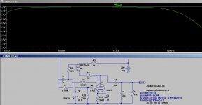
I have attached the output of what really happens - with the correct load of 47K. Now the gain is 11.6 with the bypass (or a LED), and 6 with no bypass.
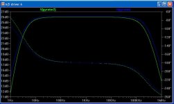
What also shows up is that if a power valve is driven (as Ale also specified) a 50pF load rolls off the unbypassed circuit to -3dB at 26kHz, and 18kHz for 150pF. This is because the unbypassed cathode resistor increases the triode's anode resistance too. The resulting circuit would give very poor results in any real world application, and is best consigned to the waste basket - or /dev/null, for Linux hackers.
Attachments
You're right - I forgot about the 47K load on the output That has nothing to do with "hazards of simulation" though. I would've gotten the same result hand-calculating it.
That begs the point though, why even use a CCS at all for driving such a low impedance reactive load? Rolloff is substantial even with the cathode bypassed. In fact, there is substantial rolloff (nearly 1db by 20khz) even without any extra load capacitance, simply due to the capacitance of the tube and the transistor. If the CCS is replaced with a suitable resistor (70-75K), the output impedance is improved, as is frequency response, even with a capacitive load. Gain is still 10.5 with a bypassed resistor or diodes, respones is flatter, and the transistor CCS is eliminated which is A Good Thing™. Of course, as I mentioned that does still require either a capacitor or diodes in the cathode circuit - pick your poison there. I'm not convinced that diodes are sonically benign compared to a capacitor, especially a good capacitor.
Back to the gyrator, it or any CCS load really only makes sense when the absolute maximum gain is needed from the single stage(which is seldom if ever the case) AND it is being fed into a very high impedance load, preferably DC coupled to the grid of another small signal tube. If the signal needs to drive a power tube, then a direct-coupled CF would make sense as it isolates the CCS-loaded stage from the highly capacitive power tube grid while having negligible capacitance itself. At least this way a capacitor or diodes in the cathode circuit can be avoided without any undue gain loss
That has nothing to do with "hazards of simulation" though. I would've gotten the same result hand-calculating it.That begs the point though, why even use a CCS at all for driving such a low impedance reactive load? Rolloff is substantial even with the cathode bypassed. In fact, there is substantial rolloff (nearly 1db by 20khz) even without any extra load capacitance, simply due to the capacitance of the tube and the transistor. If the CCS is replaced with a suitable resistor (70-75K), the output impedance is improved, as is frequency response, even with a capacitive load. Gain is still 10.5 with a bypassed resistor or diodes, respones is flatter, and the transistor CCS is eliminated which is A Good Thing™. Of course, as I mentioned that does still require either a capacitor or diodes in the cathode circuit - pick your poison there. I'm not convinced that diodes are sonically benign compared to a capacitor, especially a good capacitor.
Back to the gyrator, it or any CCS load really only makes sense when the absolute maximum gain is needed from the single stage(which is seldom if ever the case) AND it is being fed into a very high impedance load, preferably DC coupled to the grid of another small signal tube. If the signal needs to drive a power tube, then a direct-coupled CF would make sense as it isolates the CCS-loaded stage from the highly capacitive power tube grid while having negligible capacitance itself. At least this way a capacitor or diodes in the cathode circuit can be avoided without any undue gain loss
Back to the gyrator, it or any CCS load really only makes sense when the absolute maximum gain is needed from the single stage(which is seldom if ever the case) AND it is being fed into a very high impedance load, preferably DC coupled to the grid of another small signal tube.
A cascoded current source is pretty handy for driving a low impedance load via the mu follower output. Can be configured as a gyrator too. Worked nicely for me here: http://www.diyaudio.com/forums/tubes-valves/169428-unholy-alliance-phono-amp-3.html#post2372139
Sheldon
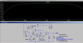
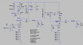
I have adjusted now the cascoded gyrator from previous post to my supply levels and also simulated the 45 output valve circuit (fixed bias) with a 220k resistor and an equivalent capacitance of about 50pF.
The optimal operating point for minimum distortion at full drive (anode voltage to around 100Vpp) is Va=260V and Ia=7mA based on my previous tests on a breadboard driver setup.
The gyrator 1 (left circuit) is Wavebourn's and the gyrator 2 (right) is the mosfet version that many are using as well.
If I connect the output of the gyrator 2 from the mosfet source, the setup is now a mu-follower which I read is better for output valve drivers. You can see in the simulations that the frequency response is improved if you connect the output capacitor in the mosfet source and not in the 6J5 anode.
I'm planning to build both version so I can test and listen to differences.
Would you recommend mu-follower? Any changes before I etch a couple of PCBs?
Also, have seen others bypassing the LEDs with a good capacitor. I have a couple of 33uF PIO which could use. They don't impact clearly on the frequency response due to the low dynamic resistance of the LED arrays, however I bet they do contribute to the sound. Any recommendations based on your experience?
Thanks for the help....
Ale
Attachments
If I connect the output of the gyrator 2 from the mosfet source, the setup is now a mu-follower which I read is better for output valve drivers. You can see in the simulations that the frequency response is improved if you connect the output capacitor in the mosfet source and not in the 6J5 anode.
No disadvantage to the mu follower, but much lower output impedance.
Sheldon
No disadvantage to the mu follower, but much lower output impedance.
+better PSRR, +less of parts that means lower cost and higher reliability.
On currents higher than 10 mA I prefer version number 2 (source follower configuration), on lower currents I prefer version 1 (P-type configuration).
Hi Sheldon,
Are you referring to the mu-follower as the one with lower output impedance?
Thanks, Ale
PS: I'm keen to replicate your DHT RIAA preamp. May be my next project!
Yes. And to the PS: It's a nice little pre.
Sheldon
+better PSRR, +less of parts that means lower cost and higher reliability.
On currents higher than 10 mA I prefer version number 2 (source follower configuration), on lower currents I prefer version 1 (P-type configuration).
Hi Anatoly,
You have been away for some time! Rod has kindly helped me out with your gyrator. Now I got the basics for SMD soldering for the bsp225 MOSFET.
Any particular reason why you prefer version 1 on lower currents?
Thanks
Ale
Any particular reason why you prefer version 1 on lower currents?
Properties of devices I can get in physical reality.
I myself don't like to solder SMD devices... But that BSP225 are quite good, in terms of voltage and capacitances. And I have a reel of them.
Last edited:
I like version 2 and have used it on a number of occasions...
To me, its simplicity and effectiveness wins through....
Which devices do you use for currents around 5 mA?
- Status
- This old topic is closed. If you want to reopen this topic, contact a moderator using the "Report Post" button.
- Home
- Amplifiers
- Tubes / Valves
- Help with gyrator