Lynn Olson made a couple of Class A DHT push pull amps, they were however 15 watt. However the information he provides will be very useful to you:
The Amity, Raven, and Aurora
The Amity, Raven, and Aurora
half of 4k ct is 2k, 400 plate volts so the math would be:
400/2000=.2 amps
It is better to speak of "4k plate-plate".
Halve the 4k primary related to the secondary is not 2k but 1k.
I guess you know that the general rule for class A is that both tubes conduct during the full cycle.
For OT lets use 4k CT and aiming for about 35watts, 17.5w per tube
You might want to study some theory on class A operation first. The first thing you will learn is that the max theoretical efficiency for an ideal class A amp is 50%. That means that in order to get 35 watts, you need to burn 70 watts at idle. Since Pdmax of a 6L6GB is 19-22 watts (depending on who's data sheet you read), you have quite the shortfall unless you start paralleling tubes.
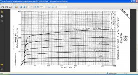
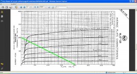
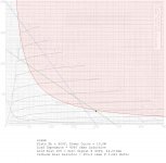
I second Defiant's suggestion, read some more. The valve wizard site is a good starting point. I plotted the load lines (using a program I wrote) using your parameters, and I don't see how you can operate at 400V.
I am new to this myself, and I don't know what the curves on your graph are showing. Usually, the grid voltage is negative, as in the graph I used.
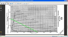
To answer your question about the power curve, P = E x I, or put another way, I = P / E. So, start at 100V and at every 25V increment calculate the current, and put a dot on the graph. When you get up to say 600V, simply connect the dots.
I am new to this myself, and I don't know what the curves on your graph are showing. Usually, the grid voltage is negative, as in the graph I used.
To answer your question about the power curve, P = E x I, or put another way, I = P / E. So, start at 100V and at every 25V increment calculate the current, and put a dot on the graph. When you get up to say 600V, simply connect the dots.
Attachments
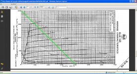
The valve wizard method cited above is good as an approximation but it is not the correct way to do this. The only way to do this correctly is composite curves (this is covered over a few chapters in Radiotron Design Handbook). Practically, composite curves are very tedious to make, since changing idle current forces you to completely re-draw the curves. Valve Wizard's is a good easy method, just keep in mind that you might not get exactly the power out that you predict.
Also, if you are going to make a class A push-pull amp, most start with a higher impedance load, I would say 6-10k. To make a class A amp with the transformers you are talking about will require pretty low idle plate voltage. You have to bias it so that it has equal positive and negative swing for it to be class A.
Also, if you are going to make a class A push-pull amp, most start with a higher impedance load, I would say 6-10k. To make a class A amp with the transformers you are talking about will require pretty low idle plate voltage. You have to bias it so that it has equal positive and negative swing for it to be class A.
It is better to speak of "4k plate-plate".
Halve the 4k primary related to the secondary is not 2k but 1k.
I guess you know that the general rule for class A is that both tubes conduct during the full cycle.
But since both tubes are working into the same 1k load at the same time it makes sense to draw the load line as a 2k load line since they are sharing it equally for class A operation.
You might want to study some theory on class A operation first. The first thing you will learn is that the max theoretical efficiency for an ideal class A amp is 50%. That means that in order to get 35 watts, you need to burn 70 watts at idle. Since Pdmax of a 6L6GB is 19-22 watts (depending on who's data sheet you read), you have quite the shortfall unless you start paralleling tubes.
Ok so I did do some reading last night
 and I think I have a better understanding on the topic but still have some questions. I actually use a deluxe reverb right now because it is only 20 watts, so if I can get 20 watts from a 6l6gb push pull class A amp that would be perfect.
 I am kind of a hands on person and don't do that well with books (serious A.D.D.) but I like to think I can pick things up quickly. One area that my brain is trying to absorb is say you have an amp biased in AB territory and you start to bias it into class A the B+ current swing goes away. I just need to picture what is going on in my head to understand better.
I know I am not an expert and may annoy some experts on here but I will take the heat in order to learn

- Status
- This old topic is closed. If you want to reopen this topic, contact a moderator using the "Report Post" button.
- Home
- Amplifiers
- Tubes / Valves
- Push Pull Class A