The valve wizard method cited above is good as an approximation but it is not the correct way to do this. The only way to do this correctly is composite curves (this is covered over a few chapters in Radiotron Design Handbook). Practically, composite curves are very tedious to make, since changing idle current forces you to completely re-draw the curves. Valve Wizard's is a good easy method, just keep in mind that you might not get exactly the power out that you predict.
Also, if you are going to make a class A push-pull amp, most start with a higher impedance load, I would say 6-10k. To make a class A amp with the transformers you are talking about will require pretty low idle plate voltage. You have to bias it so that it has equal positive and negative swing for it to be class A.
Ok after reading I agree on the higher impedence and have been working with 6.6k primary. And so to be class A and get equal positive and negative swing than you want the bias to be in the middle of the graph?
In a class AB amp when high signal levels are applied one tube goes into cut-off and therefore half of the primary is not part of the circuit. What make one tube go into cut-off? Is it the negative side of the AC signal that changes the grid voltage?
when the grid goes negative enough(as plate voltage climbs), it cuts off the flow of electrons completely.
Ok after reading I agree on the higher impedence and have been working with 6.6k primary. And so to be class A and get equal positive and negative swing than you want the bias to be in the middle of the graph?
Yes, you could bias anywhere on that line, but it would not be class A if you choose a bias point that allows a tube to swing into cutoff. If you bias at a higher current and lower voltage you will just be limiting your max output power.
If you want to play around with composite curves without the tedious curve drawing you could purchase John Broskie's push pull calculator software. It does the work for you. However, it only does triodes and triode connected pentodes. However, you still might still learn from it even though it won't do the pentode curves you are dealing with.
Last edited:
How does one go about setting an amp up to run in class A. I am bad with load lines for power tubes so if someone can get me started that would be great.
If you want to design for Class A, PP, the first thing you need is a final that can actually operate in Class A. A good many types can't do it. The TV HD finals all have the most linear part of their characteristic well into red plate territory. They sound terrific as Class A amps for a few minutes until the glass melts.
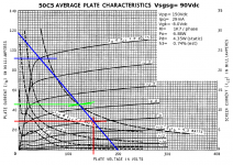
The way to design for Class A is shown here (attached). The 50C5 was one of those types designed for Class A, as it was intended for use as a SE final for AM BCB radios, cheap record players, home intercoms, etc. -- applications not requiring excellent sonic performance, and most often designed to run from a DC rail derived directly from the AC mains (a really bad idea). Still, the spec sheet is very odd, in that it provides two sets of plate characteristics: the mostly used one with V22= Vpp= 110Vdc, and a more linear characteristic with V22= 90Vdc. So the designers anticipated this type's being used for applications offering better sonic performance. (The choice of V22= 90Vdc seems deliberate in that the VR-90 voltage regulator tube operates at 90Vdc.) As always, best performance with pents results from regulated, Lo-Z screen supplies.
There are no specs for PP operation. So you need to draw up your own loadlines.
From the spec sheet:
Pd= 5.5W
Vpp= 135Vdc (max)
Given that, the plate bias current should be limited to ~0.8Pd(max) or 4.4W. Some slight spec busting gets a decent loadline, so increase Vpp to 150Vdc, and figure Ip= 29mA. Vgk= -8.0Vdc
Add that (red) to the plate characteristic. Draw the AC loadline (blue) so that it passes through the Vgk= 0 line above the "knee" to keep operation inside the saturation region, intersects the DC loadline as shown, and crosses both axises. It hits at about Vpk= 200Vdc, and Ip= 0.118A. You don't have to worry that the loadline seems to be exceeding the DC rail voltage, as this is definitely a property of inductance. In SE, Class A, the plate voltage will exceed the rail voltage, and would double it if OPTs were ideal. They never are, but you can come quite close in practice.
This gives:
Rl= 200 / 0.118= 1695R (1700R design nominal) as the load per phase.
Since the VT is always conducting, you do, indeed, have Class A operation. Class A, PP operation is a balanced, two-phase system:
Va= Vp * cos(wt)
Vb= Vp * cos(wt + 180)= -Vp * cos(wt)
And becomes the equivalent of: 2Vp * cos(wt) (single phase equivalent)
The OPT therefore needs to match the secondary load to: 2 * Rl/phase, or:
2 X 1700= 3400R (P-2-P)
Since both plate loads are in series. Figuring output power:
Idiff= 92 - 2 (read plate currents at Vgk= 0 and Vgk= -16V)
Irms= Idiff / sqrt(2)= (90E-3) / sqrt(2)= 63.64E-3 Arms
Po= I^2R= (63.64E-3)^2 X 1700= 6.89W (Theoretical: doesn't consider non-ideal OPT behavior: copper and core losses, less than ideal mutual coupling.)
As for the actual design, you could build it in the usual manner: gainstage --> splitter --> finals. Since the finals will stay in Class A, you could also make the finals into a self-splitting design as an LTP with an active tail load.
To do that, make Itail= 60mA. This will sacrifice some output, as the max plate current will be limited to Ip= 60mAp Or:
Ip= 60E-3 / sqrt(2)= 42.43E-3Arms
Po= (42.43E-3)^2 X 1700= 3.1W
That's still a respectable output for small speeks or highly efficient ones. The self-splitting PA will distort badly if you try to get more output than that.
As for sonic performance, that's a big unknown. If actually doing a project like this, it's always a good idea to spend at least a week listening for a couple hours a day while running open loop. Hear what sonic defects you can identify (aside from the expected bass under damping, due to the high rp of any pentode) before deciding if you'll need gNFB, or if some local NFB would also be beneficial. Different finals have different distortion profiles, and some are simply better than others. Types like the 6V6 make mainly h3, and just sound "edgy" or overly "aggressive", whereas others (807) like to make more h5 and higher, and produce a lot of that "pentode nastiness" and definitely need the extra help of local NFB in addition to gNFB.
If you want premium performance from a PP 50C5 amp, that definitely means springing for a custom designed OPT, as the OPTs left over from "the day" were usually used for cheap applications, and are absolutely hideous. This was also by design, as the DC made directly off the AC mains was typically quite dirty due to inadequate filtration, and lousy OPTs had cutoff frequencies well above 60Hz to attenuate the annoying hum.
Attachments
Miles, Mockingbird is talking about making a gee-tah amp, not a hi-fi amp. Which he neglected to mention until post #19  Not to be too harsh, but it seems a lot of guitar amp guys miss the description at the top of this section that says:
"Tubes / Valves All about our sweet vacuum tubes Threads about Musical Instrument Amps of all kinds should be in the Instruments & Amps forum" (emphasis mine).
There is a reason hi-fi and guitar amps are separated into different forums - they are very different animals that have very different end uses.
Not to be too harsh, but it seems a lot of guitar amp guys miss the description at the top of this section that says:"Tubes / Valves All about our sweet vacuum tubes
Threads about Musical Instrument Amps of all kinds should be in the Instruments & Amps forum" (emphasis mine).There is a reason hi-fi and guitar amps are separated into different forums - they are very different animals that have very different end uses.
Miles, Mockingbird is talking about making a gee-tah amp, not a hi-fi amp. Which he neglected to mention until post #19
"Tubes / Valves All about our sweet vacuum tubes
There is a reason hi-fi and guitar amps are separated into different forums - they are very different animals that have very different end uses.
Yeah yeah I hear what you are saying but it started out just with theory type help with no project in mind. Miles' post helped a great deal and I appreciate him taking his time to help me instead of nit-pick. Post 19 was me merely thinking out loud about what I could do in the future. This post was for me to gain a better understanding of using a datasheet to bias a tube for class A operation.
I have a bunch of 6l6's so I was just using them for the example whether they go in Hi-Fi or not. I don't have a PP 6l6 guitar amp because most are all class AB and put out too much wattage for my needs. But after thinking about it, if running the 6l6's in class A I can get less watts which is what I want. If I do decide to start a project and make a 6l6 class A guitar head than I will definately be posting in the instruments and amp thread.
Last edited:
- Status
- This old topic is closed. If you want to reopen this topic, contact a moderator using the "Report Post" button.
- Home
- Amplifiers
- Tubes / Valves
- Push Pull Class A