Not an expert on redplating, so I'm a little baffled by an observation.
I have a couple of old 6L6GBs that I plugged into an amp. The amp is PP UL, AB1, fixed bias, 470V B+. Biased the 6L6s to 55mA each and they barely glow a bit at the crease where the metal is bent at 90 degrees (inside corner). OK, I figure that's normal, metal is probably just a bit thinner there and running close to max dissipation.
But then I apply signal and as I get to max power, the redness goes away. Tubes work fine, produce clean power, looks perfect on the scope. Why are the tubes dissipating LESS at max power? Supply is not regulated and sag is negligible under full power (maybe 10V) and both PT and OPT run cold at full power.
What am I forgetting?
For pure Class A the power drawn from the supply does not change with signal. All that happens is that up to half of it gets sent to the load, so there is less power left to heat up the valve.
Class AB complicates things, but the general idea that power is diverted to the load still applies.
Class AB complicates things, but the general idea that power is diverted to the load still applies.
You're forgetting that 6L6GB's have a max dissipation of 22 watts. 470Vx0.055A=25.85W. Assuming you measured the current at the cathode, then some of this current is coming from the screen, but you are still over-dissipating the plate. 470V is also well in excess of the max plate voltage rating of a 6L6GB (400V max), and WAY in excess of the max screen rating (300V max). This is why you are getting some plate color.
As to why plate dissipation drops as you approach max power, that is a common characteristic of class AB and class B operation. Depending on where the quiescent point is set, the max drive, and the load, the dissipation of the output devices (tube or transistor) will increase with signal up to some percentage of max power (for class B operation) and then decrease as you approach max power. Since you are biased quite hot you will see the dissipation drop below quiescent at some percentage of max power and continue dropping up to 100% power.
As to why plate dissipation drops as you approach max power, that is a common characteristic of class AB and class B operation. Depending on where the quiescent point is set, the max drive, and the load, the dissipation of the output devices (tube or transistor) will increase with signal up to some percentage of max power (for class B operation) and then decrease as you approach max power. Since you are biased quite hot you will see the dissipation drop below quiescent at some percentage of max power and continue dropping up to 100% power.
Thanks guys.
Defiant, I'm not forgetting that part. Actually these are RCA tubes and I believe the data sheet says 19W plate dissipation. The amp is designed for 6L6GC, I was doing an unrelated experiment when I noticed the redplating behavior.
Dissipation did NOT increase with signal at all, it stayed constant from idle to about 60% power and decreased gently from there to full output.
Thanks guys.
Defiant, I'm not forgetting that part. Actually these are RCA tubes and I believe the data sheet says 19W plate dissipation. The amp is designed for 6L6GC, I was doing an unrelated experiment when I noticed the redplating behavior.
The plates are glowing due to excessive dissipation. 6L6GC's and related tubes (7027A, 7581, 7581A) have a higher dissipation rating due to the use of different plate material (explosive-clad tri-metal alloy in the GC vs plain nickel in the GB and earlier) which spreads and radiates heat more effectively. The plate is also larger in the GC. In other words, there are very real differences, and very real limits on the earlier 6L6 types.
That is due to the high bias current you are running. Class B operation will show the increase-then-decrease of dissipation as you approach full power, while class A will slowly decrease as you approach full power. Class AB1, which you are running) falls somewhere in-between depending on bias current. The behavior you are seeing is completely normal for your operating conditions.Dissipation did NOT increase with signal at all, it stayed constant from idle to about 60% power and decreased gently from there to full output.
Why are the tubes dissipating LESS at max power?
As defiant stated this is a totally normal thing.
A class A amp dissipates the most power at Idle and the least at full power. This is because ALL of the energy from the plate supply is dissipated in the tubes and none goes to the speaker at idle. As you turn it up the current stays constant, but some of the power supplies energy goes to the speaker.
A true class B amplifier dissipates NO power at idle since neither output tube is conducting. As you apply signal the tubes will start to work and the dissipation will increase reaching maximum at full power output.
A class AB amplifier falls in between these two extremes. It dissipates power at idle since there is an idle current and no power output. It will also dissipate power at full output. A well designed class AB mmplifier might get 60% efficiency at full power output since considerable power is being transferred to the speaker and the tubes are swinging from fully saturated to fully cutoff. Each tube is cut off for almost 1/2 of the time. As the power output is reduced the time in conduction for each output tube increases to 100% at idle, and the tubes spend no time in saturation so they dissipate more.
All class AB amps exhibit this effect but the power level at which the dissipation reaches maximum depends on the load line and bias conditions.
My hot-rodded red board (125 WPC) will show some redness at about 50 WPC, yet none at full power. It does not show any redness with music no matter how loud it is cranked since music has peaks 10 to 20 db below the average power level.
new 6l6gb's might have different specs but old 6l6gb's have max ratings for screen 270v and plate 360v. I don't know what datasheet defiant is looking at but I am looking at RCA's datasheet. I had a thread not to long ago about the 6l6gb tube and it's capabilities and the consensus was that arcing can occur with the high voltages because the heater is so close to the plate. And I am no expert on class of amps but I was under the impression that usually to reach class A operation the plate voltage is usually lower than most AB setups. 470v class A for a 6l6gb sounds high and I would expect tube life to be short.
Last edited:
As the power output is reduced the time in conduction for each output tube increases
That's the part I was forgetting. Thank you.
Famous, you are correct, but this isn't about tube specs, I know I was abusing the tubes. It was about the power dissipation curve, which hadn't occurred to me because I don't redplate my tubes very often. I need to get out on the wild side of the specs more often
")
A true class B amplifier dissipates NO power at idle since neither output tube is conducting. As you apply signal the tubes will start to work and the dissipation will increase reaching maximum at full power output.
That is incorrect. A class B output stage will reach max dissipation at it's 50% efficiency level, which happens at an RMS voltage of 2Vb/π. This equates to an output power level of 40% theoretical max. The reason I say "theoretical" is because no tube or transistor can swing completely to the rail, so a bit more math with the load lines for the tube or transistor along with the actual loading is needed to determine where this point actually lies and what the overall efficiency will actually be. But, for discussions sake we can stick with the statement that a class B or very low biased class AB will reach max dissipation in the 40-ish percent rated power region.
Cool! I was more curious on where defiant got his specs from because I was trying to find the datasheet for the sovtek 6l6gb.
I might start a thread on class A because my mind is still a little confused.
That was off of a Tung-Sol data sheet. The RCA sheet shows a bit more conservative rating. Apparently, Tung-Sol uprated the tube a bit while RCA stuck to the old metal shell ratings. Metal tubes are less efficient at dissipating heat since they have to radiate the heat from the plate to the shell, which then has to dissipate the heat by convection and re-radiation. By contrast, glass tubes can dissipate heat much more effectively since much of the radiant heat from the plate passes through the glass. Likewise, the bases of the metal shell tubes have higher leakage current vs their glass bottle counterparts, so they cannot tolerate as much voltage before they risk bias instability. The RCA sheet is a bit older than the Tung-Sol sheet, so I don't know if they bumped the GB's rating later or if they kept the conservative metal shell rating while Tung-Sol (and perhaps others) bumped the ratings...
A class B output stage will reach max dissipation at it's 50% efficiency level, which happens at an RMS voltage of 2Vb/π.
Where is this voltage measured and what are Vb and n?
That is incorrect. A class B output stage will reach max dissipation at it's 50% efficiency level.....The reason I say "theoretical" is because no tube or transistor can swing completely to the rail
This may be true. I haven't explored the theory, just recalling my experience. True class B amps don't exist in the HiFi world due to the severe crossover distortion.
I have built a few screen drive test amps where the idle current is 5 mA or less. Screen drive may not be the typical case but the few that I have made seem to follow the same trend. The harder you push them the hotter they get. 75% plate efficiency is not hard to achieve and I have seen 80% on a couple of designs. This allowed over 100 watts to flow from a pair of 6BQ6GT's without redness. Attempting to push 125W caused a flashover and tube failure. The 6BQ6GT is rated at 11 watts dissipation and I was using a pair of small RCA's that I got for 98 cents each during the AES tube sale a few years back.
very low biased class AB will reach max dissipation in the 40-ish percent rated power region.
Most HiFi amps are biased well into class AB. The idle current can be half the tubes dissipation or even higher. There will be a region at the low end of the power spectrum where both tubes are conducting and the amp is operating in class A. In this region the tube dissipation drops as the power output increases. The plate efficiency is zero at idle and rises slowly in this region. The efficiency rises quicker as one of the tubes enters cutoff for part of the cycle and reaches maximum at full power output.
Since I have been tinkering with maximum power output designs I have explored ways to improve efficiency without adding excessive distortion. About the only conclusion I can reach is that the output stage efficiency climbs non linearly as the power output is increased, and the power dissipation peaks somewhere between zero and full power with most amps reaching maximum near half power. The max dissipation point depends on idle current, load line, transformer losses, and tube type. The efficiency and max dissipation point will also change if grid current is allowed since the tube can pull its plate closer toward ground. Most of my designs use mosfet drive allowing considerable grid current.
I build linear RF power amps (solid state) for advanced modulation types like LTE in my job. I find that the same generalities about output stage efficiency and dissipation apply here too.
That was off of a Tung-Sol data sheet. The RCA sheet shows a bit more conservative rating.......I don't know if they bumped the GB's rating later or if they kept the conservative metal shell rating while Tung-Sol (and perhaps others) bumped the ratings...
The RCA and Sylvania data sheets are using the "Design Center" rating system. The Tung Sol data sheets specify "Design Maximum" which is usually about 10% higher. The manufacturers switched to the design maximum rating system in 1957. This is explained on page 95 of the RCA RC-30 receiving tube manual which can be downloaded from Pete's site.
Most people who follow my experiments know that I have my own rating system called the Designed Meltdown system.
Where is this voltage measured and what are Vb and n?
Voltage is measured at the plate. Vb=plate supply voltage. The second symbol is not an "n", it is "π" (pi).
I haven't explored the theory......and I have seen 80% on a couple of designs.
Only if you were running a non-linear mode like class C or class D. The mathematical maximum efficiency for a class B amplifier is 78.5%, and no tube or transistor will ever actually reach it since it would require the output devices to swing to the rail. Transistors can come close (at the cost of high crossover distortion), but tubes will seldom get over the mid-high 60% range.
Oh yeah, I forgot about the rating system changeThe RCA and Sylvania data sheets are using the "Design Center" rating system. The Tung Sol data sheets specify "Design Maximum" which is usually about 10% higher. The manufacturers switched to the design maximum rating system in 1957. This is explained on page 95 of the RCA RC-30 receiving tube manual which can be downloaded from Pete's site.
An externally hosted image should be here but it was not working when we last tested it.
Last edited:
new 6l6gb's might have different specs but old 6l6gb's have max ratings for screen 270v and plate 360v. I don't know what datasheet defiant is looking at but I am looking at RCA's datasheet.
That rating is due to the 7AC pinout. For whatever dumb@55ed reason, the plate is connected to pin #3 and the heaters to pins #2 and #3. This puts the highest voltage right next to the lowest voltage. This invites flashover if you try to exceed the Vpp= 360Vdc max rating.
The 807, the otherwise identical type designed for RF, not audio, that has a plate cap connection can operate up to Vpp= 750Vdc (the limit for oxide type cathodes) I guess the designers weren't figuring on anyone's wanting to get more than about 30W from 6L6 audio amps, as opposed to the 120W of audio that you can get from Class B, PP 807s operated at 750Vdc.
Voltage is measured at the plate. Vb=plate supply voltage. The second symbol is not an "n", it is "π" (pi).
Thanks for the clarification. So when you say Vb (rms), is that the AC + DC on the plate? "Plate supply voltage" to me would mean just the idle DC voltage, so I'm not sure about "rms".
Or do you mean that max dissipation occurs when the AC signal on the plate reaches the value Vb/pi, where Vb is the idle plate DC?
Last edited:
I want to clarify some statements I made from my memory earlier today. I was at work posting from my phone without access to my lab, my notes, or my web site.
The amplifier that I built several years ago and measured 80% efficiency did not make 80%, it made 76.2%. (80 watts of audio for 105 watts of DC). This is not bad for a tube amp and I have seen higher on screen driven sweep tube amps. The amp test in question is reported at the bottom of this page:
6AV5GA testing
I am aware of this theoretical maximum, and it is indeed true that a good tube amp design usually runs in the 60 to 65% efficiency range. The theoretical maximum is only valid at 0% distortion and tube amps do not operate at 0% distortion.
I, and many other tube amp builders specify maximum power output at an arbitrary distortion figure, usually 5% for higher powered amps. An amplifier can exceed the theoretical 78.5% maximum efficiency figure if operated at 5% distortion since the distortion is usually clipping caused by saturating output tubes. Taken to extreme a fully staurated amp putting out pure square waves can approach 100% efficiency.
A few years ago I and several other experimenters here went into a feeding frenzy over a tube sale at AES where big sweep tubes went for as little as 98 cents. I grabbed up quite a few and performed some extreme testing in this thread. The fun starts on page 9.
http://www.diyaudio.com/forums/tubes-valves/128533-tube-sale-aes.html?highlight=tube+sale+aes
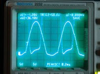
On page 11 there are scope shots of the plate and screen voltages of a tube being tested in screen drive at high power. I posted the photos here.
The first picture shows one scope probe on the screen grid, and the other on the plate. This one is with the amp cranked to 130 watts at about 25% distortion (hard clipping). The scale is 50 volts per division, and zero is the second division from the bottom. The screen drive voltage goes from about -15 volts to +250 volts. The plate voltage touches ZERO and settles to about +35 before heading to some extreme positive voltage above 1KV. The non flatness is caused by OPT saturation effects.
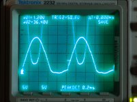
The second picture is the same amp operated at 80 watts and 4% distortion. The plate is pulled down to 40 volts on an undistorted sine wave peak.
The plate voltage can swing from zero to twice the B+ if the tube is pushed into hard clipping. It will also come within 40 volts of the rails when operated in a reasonable manner. This allows efficiency figures approaching the theoretical maximum. Both of these examples were screen driven tube amplifiers operated in near class B. In both of these cases the maximum dissipation was coincident with maximum undistorted output power. The dissipation drops as the tubes are pushed into clipping. Maximum dissipation was verified by observing the plate color in a dark room.
All of this means nothing with music since the amp is operated at close to idle conditions. Most music has between 10 to 20 db of "crest factor" which is the difference between the peak and the average power levels. So if you turn a 100 watt amp up until it clips on music peaks, the average power level will be between 1 and 10 watts!
The amplifier that I built several years ago and measured 80% efficiency did not make 80%, it made 76.2%. (80 watts of audio for 105 watts of DC). This is not bad for a tube amp and I have seen higher on screen driven sweep tube amps. The amp test in question is reported at the bottom of this page:
6AV5GA testing
The mathematical maximum efficiency for a class B amplifier is 78.5%, and no tube or transistor will ever actually reach it since it would require the output devices to swing to the rail.
I am aware of this theoretical maximum, and it is indeed true that a good tube amp design usually runs in the 60 to 65% efficiency range. The theoretical maximum is only valid at 0% distortion and tube amps do not operate at 0% distortion.
I, and many other tube amp builders specify maximum power output at an arbitrary distortion figure, usually 5% for higher powered amps. An amplifier can exceed the theoretical 78.5% maximum efficiency figure if operated at 5% distortion since the distortion is usually clipping caused by saturating output tubes. Taken to extreme a fully staurated amp putting out pure square waves can approach 100% efficiency.
A few years ago I and several other experimenters here went into a feeding frenzy over a tube sale at AES where big sweep tubes went for as little as 98 cents. I grabbed up quite a few and performed some extreme testing in this thread. The fun starts on page 9.
http://www.diyaudio.com/forums/tubes-valves/128533-tube-sale-aes.html?highlight=tube+sale+aes
On page 11 there are scope shots of the plate and screen voltages of a tube being tested in screen drive at high power. I posted the photos here.
The first picture shows one scope probe on the screen grid, and the other on the plate. This one is with the amp cranked to 130 watts at about 25% distortion (hard clipping). The scale is 50 volts per division, and zero is the second division from the bottom. The screen drive voltage goes from about -15 volts to +250 volts. The plate voltage touches ZERO and settles to about +35 before heading to some extreme positive voltage above 1KV. The non flatness is caused by OPT saturation effects.
The second picture is the same amp operated at 80 watts and 4% distortion. The plate is pulled down to 40 volts on an undistorted sine wave peak.
The plate voltage can swing from zero to twice the B+ if the tube is pushed into hard clipping. It will also come within 40 volts of the rails when operated in a reasonable manner. This allows efficiency figures approaching the theoretical maximum. Both of these examples were screen driven tube amplifiers operated in near class B. In both of these cases the maximum dissipation was coincident with maximum undistorted output power. The dissipation drops as the tubes are pushed into clipping. Maximum dissipation was verified by observing the plate color in a dark room.
All of this means nothing with music since the amp is operated at close to idle conditions. Most music has between 10 to 20 db of "crest factor" which is the difference between the peak and the average power levels. So if you turn a 100 watt amp up until it clips on music peaks, the average power level will be between 1 and 10 watts!
Attachments
Thanks for the clarification. So when you say Vb (rms), is that the AC + DC on the plate? "Plate supply voltage" to me would mean just the idle DC voltage, so I'm not sure about "rms".
Not Vb(RMS); Vb is the DC voltage on the plate of the idling tube. Being DC, there is no RMS component. RMS=Root Mean Square, and only relates to a signal with an AC component. Also, I blew it - peak voltage, not RMS, is the result of the calculation.
An externally hosted image should be here but it was not working when we last tested it.
Exactly, except that the formula is 2Vb/π, not Vb/π. Also, i seem to be forgetting myself - that would be peak voltage, not RMS. Sorry bout that.... it's been a while since I actually had to use these formulasOr do you mean that max dissipation occurs when the AC signal on the plate reaches the value Vb/pi, where Vb is the idle plate DC?
So, 50% efficiency and max dissipation in a class B stage happens when the peak signal plate voltage is 2Vb/π, which equates to 63.66% of the quiescent plate voltage. If you had, say, 400V on the plate and watched the signal with a scope (say a pure sine wave for simplicity), then you would me at max dissipation at a level of 400x1.6366=654.64V peak. This equates to 40% of the maximum theoretical power of the amp. Plate dissipation drops above or below this power level.
Remember, this ONLY applies for class B output stages.
Last edited:
then you would me at max dissipation at a level of 400x1.6366=654.64V peak.
You lost me here. Don't you mean 2x400/3.14=255V?
- Status
- This old topic is closed. If you want to reopen this topic, contact a moderator using the "Report Post" button.
- Home
- Amplifiers
- Tubes / Valves
- Redplating anomaly?