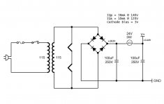
I'm designing a two channel tube amp using 60FX5's. I am using an isolation transformer and when rectified it gives me 161 VDC. I want to run the tubes with 140V on the tube and a cathode bias of 3V for a total of 143VDC. So, I need to drop 18V. The Q point of the circuit will draw 36mA plus 10mA from the screen per channel, for a total of 92mA.
If my math is correct, a 24V 3W bulb will drop 17.6V at 92mA.
So my question is, can I use a 24V 3W lamp to drop the voltage?
I know it's not a plain old resistor, so does this effect the circuit in any way?
If my math is correct, a 24V 3W bulb will drop 17.6V at 92mA.
So my question is, can I use a 24V 3W lamp to drop the voltage?
I know it's not a plain old resistor, so does this effect the circuit in any way?
Attachments
It should be interesting as I expect that the filament's negative temperature coefficient might result result in a slightly more constant output voltage as a function of line and load variation. (Over a small range)
It can't hurt to try it and if it doesn't work as well as expected you can just replace it with a resistor down the road.. The big question is how it deals with the capacitor inrush...
It can't hurt to try it and if it doesn't work as well as expected you can just replace it with a resistor down the road.. The big question is how it deals with the capacitor inrush...
Actually modern metallic lamp filaments have a positive temperature coefficient. It's the old carbon filament predecessors that had a negative coefficient, but they're ancient history. IMO using a temperature sensitive variable resistor as a series element in the power supply is a bad idea. Regulation will suffer rather then be improved. If it was good, why is it that it's never commercially done?It should be interesting as I expect that the filament's negative temperature coefficient might result in a slightly more constant output voltage as a function of line and load variation.
Another solution: (If you are not familiar with safe electrical practise do not attempt this).
Add a 115/12.6V, 150mA, isolating transformer in 'buck' connection.
1. Connect the 115V winding in parallel with the existing transformer 115V winding.
2. Connect one end of the existing transformer secondary winding to one end of the added transformer's 12.6V secondary winding.
3. Measure the voltage across the, now combined, secondary winding. If you measure about 102.4V you can connect the combined secondary winding to your circuit.
If you measure 127.6V just swap the 12.6V secondary leads around and you should get around 102.4V.
4. Connect in the PS and measure DC out.
Last edited:
Actually modern metallic lamp filaments have a positive temperature coefficient. It's the old carbon filament predecessors that had a negative coefficient, but they're ancient history. IMO using a temperature sensitive variable resistor as a series element in the power supply is a bad idea. Regulation will suffer rather then be improved. If it was good, why is it that it's never commercially done?
DUH!!! You're absolutely right.. Have no idea what I was thinking of, well it was just before dinner.. Yeah, I'll go with that..
 And I wasn't thinking of carbon filament lamps at that particular moment in time..
 Might work great in a guitar amp!
Another solution: (If you are not familiar with safe electrical practise do not attempt this).
Add a 115/12.6V, 150mA, isolating transformer in 'buck' connection.
A very good suggestion. If I could have found an iso-xfrmer with an additional 12.6V secondary I might have gone that route. I am familiar with safe electrical practice, doesn't mean I always follow it though . I have worked with low power lasers as a hobby and high voltage xray scanners in my career.
I'm building a small iPod dock, and was actually considering not using the iso transformer. This is one of those rare instances when I decided to be safe. When I bought my house 11 years ago, I ripped out all the old wiring and re-wired the house myself, so I am confident that my outlets are wired correctly.
Cost and space are an issue for this ( my first ) tube project, and I'm trying to use as few components as possible, especially transformers.
Last edited:
You may be able to put a 24 volt zener in series with the output of the supply.
That will give you a 24 volt drop.
Zeners are noisy, not recommended here.
Could the secondary of the xfmr be carefully unwound til you reach your target voltage?
To much trouble, not enough knowledge or skill.
You may be able to put a 24 volt zener in series with the output of the supply.
That will give you a 24 volt drop.
A small power resistor will work just fine and will make a CRC input filter circuit which is going to be required to knock the ripple down sufficiently for reasonable performance..
Anything between 220 - 270 ohms should work. Use a 5W resistor..
Just found some 243 ohm 3W resistors. I think I'll skip the light bulb idea for now. I will definitely replace the resistor with a light bulb once I'm done because my curiosity has been tweaked and I need to know.
Even if it was a good thing who would buy an amp that needs a lightbulb replaced regularly.
Pilot lights on old radios used to be wired in series with the filaments. The pilot light burns out, the radio stops working. Or even worse, pilot light shorts and causes excess current through the filaments and burns the tubes out as well.
I understand your point, but I'm not selling anything. I'm making one, and only one of these for use exclusively in my house. Like most things I've made, it will end up in the basement after a year or so of use, or when I move on to a push-pull design.
I'm designing a two channel tube amp using 60FX5's. I am using an isolation transformer and when rectified it gives me 161 VDC. I want to run the tubes with 140V on the tube and a cathode bias of 3V for a total of 143VDC. So, I need to drop 18V. The Q point of the circuit will draw 36mA plus 10mA from the screen per channel, for a total of 92mA.
If my math is correct, a 24V 3W bulb will drop 17.6V at 92mA.
So my question is, can I use a 24V 3W lamp to drop the voltage?
I know it's not a plain old resistor, so does this effect the circuit in any way?
A light bulb is exactly the wrong thing to use. Their resistance is a function of temperature but it goes the "wrong" way. It is low when cold then the resistance builds. You'd be better off with a sandstone resistor.
If you are going to use a resister to drop voltage why not put that drop to good use? Add in an extra section of CRC filter. As long as you are forced to use the resistor adding just one more small 40uF cap will greatly reduce the 120Hz ripple on the B+
You may NOT need to drop voltage at all - in fact you may net even get as much as 140V. Was 161V measured under load or open circuit? Expect it to drop considerably under load.
If it IS voltage at full load, one trick that should work is to reverse the isolation transformer primary and secondary. They're wound with a small "step up" in ratio to compensate for the voltage drop under load. Reverse it and you'll get a small step down plus the normal voltage drop.
If it IS voltage at full load, one trick that should work is to reverse the isolation transformer primary and secondary. They're wound with a small "step up" in ratio to compensate for the voltage drop under load. Reverse it and you'll get a small step down plus the normal voltage drop.
- Status
- This old topic is closed. If you want to reopen this topic, contact a moderator using the "Report Post" button.
- Home
- Amplifiers
- Tubes / Valves
- Using low voltage lamp in power supply