Sounds good - what do you suggest?
Add another RC stage to the PS filtering. Like bernification said, you still want the sag in a guitar amp in order to get the desirable compression. An extra RC stage will drop your voltage, improve filtering, and make the supply sag a bit more by increasing it's series resistance.
Thank you kindly for your responses.
I read the lower HT thread...seems there are discrepancies between opinions (go figure!). I'm not using a CT in this design (although there is a tap...), and perhaps on the next build I will go with a tube rectifier.
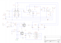
Please have a look at the revised schematic - there was a 22uf at the top left corner which I moved down to the filter section, it's easier to see this way. Do you recommend adding yet another filter cap in there? You'll see I dropped the 150uf to 47uf, but I can reduce it further to 20uf - any merit for either choice?
I did not edit the 220K and 100K plate resistors, would you have suggestions for new values? I also did not fill in the zener value...not sure of necessary wattage or voltage. My AC input was about 50V too high (275) and my HT was about 50V too high (375), measurement taken before grounding the cathodes)...all while the PT was seeing a fraction of its necessary load in the first place. Does the zener remove the votlage it is spec'd for, PLUS add load to the PT causing its secondary voltage to drop? I'd imagine this all ties into selecting the correct zerner...
I'm just looking for 'acceptable' on this...it ain't no champ!
I read the lower HT thread...seems there are discrepancies between opinions (go figure!). I'm not using a CT in this design (although there is a tap...), and perhaps on the next build I will go with a tube rectifier.
Please have a look at the revised schematic - there was a 22uf at the top left corner which I moved down to the filter section, it's easier to see this way. Do you recommend adding yet another filter cap in there? You'll see I dropped the 150uf to 47uf, but I can reduce it further to 20uf - any merit for either choice?
I did not edit the 220K and 100K plate resistors, would you have suggestions for new values? I also did not fill in the zener value...not sure of necessary wattage or voltage. My AC input was about 50V too high (275) and my HT was about 50V too high (375), measurement taken before grounding the cathodes)...all while the PT was seeing a fraction of its necessary load in the first place. Does the zener remove the votlage it is spec'd for, PLUS add load to the PT causing its secondary voltage to drop? I'd imagine this all ties into selecting the correct zerner...
I'm just looking for 'acceptable' on this...it ain't no champ!
Attachments
Last edited:
Thank you kindly for your responses.
I read the lower HT thread...seems there are discrepancies between opinions (go figure!). I'm not using a CT in this design (although there is a tap...), and perhaps on the next build I will go with a tube rectifier.
Please have a look at the revised schematic - there was a 22uf at the top left corner which I moved down to the filter section, it's easier to see this way. Do you recommend adding yet another filter cap in there? You'll see I dropped the 150uf to 47uf, but I can reduce it further to 20uf - any merit for either choice?
I did not edit the 220K and 100K plate resistors, would you have suggestions for new values? I also did not fill in the zener value...not sure of necessary wattage or voltage. My AC input was about 50V too high (275) and my HT was about 50V too high (375), measurement taken before grounding the cathodes)...all while the PT was seeing a fraction of its necessary load in the first place. Does the zener remove the votlage it is spec'd for, PLUS add load to the PT causing its secondary voltage to drop? I'd imagine this all ties into selecting the correct zerner...
I'm just looking for 'acceptable' on this...it ain't no champ!
First off, a bit of zener diode education: If you install the zener forward-biased like you have drawn in your schematic you will only get the normal diode forward voltage drop of 0.7-1V or so. Zeners get installed in the circuit reversed-bias - they are designed to avalanche at a specific voltage and maintain that voltage drop. So, if you were to use the zener you would need to reverse it. Power dissipation of a zener is easy to calculate: Take it's zener voltage and multiply it by the current flow in amperes. That is how many watts the diode will dissipate. I prefer triple overage (or more), so I would run a zener rated for at least 3 times the wattage that you calculate. If a single diode won't go that high wattage-wise, you can connect multiple lower voltage zeners of lesser wattage in series to get the combined voltage and wattage ratings you need.
Now that I said all that, I would forget the zener in your design. Replace it in your schematic with a suitable resistor, and put another 47uF cap at the output of the rectifier. The resistor value can be determined by calculations or by experimentation. Make sure you use a high enough wattage - again, I like triple or more the calculated wattage. Once you zero in on the desired plate voltage for the 6V6 the rest of the dropping string may need adjustment if the screen and 12AX7 supplies drop too much.
Finally, if you want to use a tube rectifier in your circuit it is still possible, Just replace the right-most 2 diodes in your bridge with the tube rectifier. Since you need voltage drop anyway, use a filamentary rectifier like a 5Y3. This will necessitate reducing the value of the first resistor in your filter string since the tube will make up for some of it. Also, you would want to reduce the input cap to 10uF - tube rectifiers don't like charging big input caps.
What about this claim from the HT thread; "Adding series resistance kills the dynamics and makes the amp lifeless".?
Also this design is built already - I don't want to go about installing a tube rectifier at the moment - I don't have as much wiggle room in the chassis by this point.
I can't stress the added value of the help supplied by this forum - a million times, thank you!
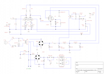
Check out the new diagram. After I add a new 47uf after the rectifier, there is a question mark value at the 2nd cap (for 6V6 screen). Keep the original 47uf there or better to reduce it further, down to 20uf? Resistor "R" is TBD. Also no word on the plate resistors? (220K,100K)
Also this design is built already - I don't want to go about installing a tube rectifier at the moment - I don't have as much wiggle room in the chassis by this point.
I can't stress the added value of the help supplied by this forum - a million times, thank you!
Check out the new diagram. After I add a new 47uf after the rectifier, there is a question mark value at the 2nd cap (for 6V6 screen). Keep the original 47uf there or better to reduce it further, down to 20uf? Resistor "R" is TBD. Also no word on the plate resistors? (220K,100K)
Attachments
What about this claim from the HT thread; "Adding series resistance kills the dynamics and makes the amp lifeless".?
Its the sort of hyperbole-laden folklore that should be eradicated unless it is backed by some verifiable technical reasoning.
What about this claim from the HT thread; "Adding series resistance kills the dynamics and makes the amp lifeless".?
That's where experimentation comes in. Remember, you can mix resistors and zener diodes to achieve the PS impedance and voltage you want. It doesn't all have to be one or the other. In fact, experiment with it and see what sounds best to you. Thats what this hobby is all about after all, whether hi-fi or gee-tah amps
Your plate resistors on the 12AX7 are suitable, but there again you can experiment. A larger value of plate resistor will drop more voltage and as a result the tube will tend to cut off at large signal amplitudes. A smaller value resistor will drop less, and will go into positive grid drive (with a time constant created by the coupling cap and resistor) at large signals. Each will sound different. A certain value will hit both ends more or less simultaneously and give a different sound as well. Also, a larger value will give more gain while a lower value gives less. It's all a tradeoff. You're input will never reach cutoff or clipping, so a larger resistor will be helpful to have more gain (but not too big - that 220k I would consider max). The second half of the 12AX7 is the one I would concentrate on experimenting with plate (and cathode) resistors.
Ok sounds good. I will digest, make all the corrections we spoke about and test the amp.
Do you have any thoughts on the OT/6V6 plate RC filter? 47 or 20uf...
I completely forgot to mention that the basis of this copy used a 12AX7 and signal was Dir-ty (fantastic though...for guitar). I have been planning to swap this tube based on application. For gee-tah, keep as is, but for "tube pre" applications, i.e. leslies, swap in a 12AU7.
Ok sounds good. I will digest, make all the corrections we spoke about and test the amp.
Do you have any thoughts on the OT/6V6 plate RC filter? 47 or 20uf....
Either will be fine. The 20 will give more sag at the expense of more ripple. If you have both then by all means try both
Hey guys,
I was proposing a zener diode from the earthy end of you bridge rectifier to ground, anode to ground and cathode to the junction of your 2 diodes. Chose a value that you need to lose (50v?).
If you need to get rid of 50 volts, 12-15 watts is what you need. Big series resistors will slow down your psu excessively, and overdamp it- destroys some of the bounce that having an output transformer will bring. I guess if you want to use series resistors ~500 ohms with 12au7, and ~900 ohms for 12ax7 will be about right.
If reducing cathode bypass caps doesn't get rid of oscillation, try a resistor between the 100k- 220k plate loads- only a couple k.
I suspect that you have no lf cutoff point in the circuit- try an rc filter between the two front end stages, this will add stability. With a 12ax7, you will have too much gain otherwise.
Experimentation is good fun, I did the same when building my first amps, but on a first build with limited experience, it drove me mad. A known diagram was a lot easier.
Good Luck
Bernie
Thank Andreas, That is priority number one!
Mouser's supply jumps from 6W to 40W.
Also the 40W are really cheap, I thought high wattage zeners are expensive..
One 51V zener spec sheet reads 40W Non-repetitive peak reverse power dissipation, and 300mW total power dissipation. I have a feeling i'm not looking at the right one. Could you link to a supplier with the correct part?
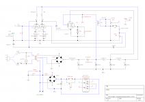
Installed 17V, 17V, 16V zeners (5watt ea) between rectifier and filters. Voltage at first filter with no 6V6 installed: 320VDC.
Installing the 6V6 reveals these values;
Cathode voltage: 16 VDC
Plate voltage: 270 VDC
Plate to Cathode: 253 VDC
Screen to Cathode: 253 VDC
Updates schematic attached.
Bypass works. Effect works, albeit very tame (which is OK at this point, also i'm using a 12AU7 at the moment), however there is a lot of intermittent snap crackle and pop and I can't really give'r for fear of damaging my output speaker.
Attachments
Last edited:
- Status
- This old topic is closed. If you want to reopen this topic, contact a moderator using the "Report Post" button.
- Home
- Amplifiers
- Tubes / Valves
- 1st build; Adding load to PT secondary