Hi:
I am planning to build TDA1541 based DAC using boards from a diyaudio member and I/V & Tube stage as posted by Thorsten Loesch in 2005 (see attached image).
I am just a beginner thus need some help. Here are two questions,
1) What changes I have to do in this Thorsten circuit if I want to try 6H30 instead of ECC88? Apart from heater current requirement, ECC88 has amplification factor of 33 and 6H30 has 15/16. Please guide in detail about the changes in circuit.
2) Is this the last version by Thorsten or is there any upgraded version? I mean this is from 2005, any 2011 version?
Regards
I am planning to build TDA1541 based DAC using boards from a diyaudio member and I/V & Tube stage as posted by Thorsten Loesch in 2005 (see attached image).
I am just a beginner thus need some help. Here are two questions,
1) What changes I have to do in this Thorsten circuit if I want to try 6H30 instead of ECC88?
Apart from heater current requirement, ECC88 has amplification factor of 33 and 6H30 has 15/16. Please guide in detail about the changes in circuit.2) Is this the last version by Thorsten or is there any upgraded version? I mean this is from 2005, any 2011 version?
Regards
Attachments
Please guide in detail about the changes in circuit.
Not much you can do about the drop in gain. Fixed bias will only have a minor effect. An active preamp may be essential.
Not much you can do about the drop in gain. Fixed bias will only have a minor effect. An active preamp may be essential.
Wouldn't a cap across Rk help improve gian?
Thanks, Sy. What you are purposing is my probable plan. However, I want to learn some without experimentingJust curious- since excellent ECC88 are easily available and the design for that tube has been worked out, why not start with the original circuit, get it working, then start experimenting once you understand its strong and weak points?
. When you fine people have established some facts/opinions by hard work, I don't want to establish them again. I am beginner (but have been reading tubes), this circuit is simple, thus from your replies I'll learn.analog_sa, thank you. can you please explain what changes you expect due to fixed bias but change to different tube, 6H30, in this circuit?Not much you can do about the drop in gain. Fixed bias will only have a minor effect. An active preamp may be essential.
I believe you are referring to increased gain if we bypass the cathode resistor with a capacitor. But what are the effects on sound quality if we increase gain this way?Wouldn't a cap across Rk help improve gian?
Kindly help me learn. What is the disadvantage of lower gain in this circuit, what is the advantage of maintaining the 33 times gain here? I am rather very confused
. With a CD player's output of 2V, I cannot use more than 1/3 of the volume control on my preamplifier. That is, gain structure is already high and most of the gain is going into drain. Some friends claim that, keeping the overall sound level constant, it sounds nicer if the volume pot is at higher end, i.e. less resistors.Besides gain, please help me understand other changes in circuit if needed with why and how explanation.
Last edited:
Hi:
The question was originally asked in digital section. I am puzzled by lack of responses. Either there were few experts on tubes there or everybody was avoiding touching Master Thorsten's work.
Nonetheless, here is information about this curcuit in Thorsten's own words as copied from audioasylum, 03/15/05.
"It is a simple ECC88/7308 with a choke or CCS load, biased negative minimally (around -0.1V) from a 47R I/V resistor (and the -2mA offset current for digital silence) and with a 10R Cathode resistor. Anode Voltage around 75V IIRC. The one added trick is an "anti sinc" filter using the most primitive methode of a parallel RLC Circuit. Good output coupling capacitor (2.2uF Mundorf Silver or AN Copper)"
Kindly help!
Wouldn't a cap across Rk help improve gian?
Barely. Close to "not at all." 10R raises the plate resistance by about 300R, and the choke impedance is thousands of time higher.
My advice still stands- build it as-is first, get a feel for what it does well and what it doesn't, then direct your experimentation toward the latter, rather than deciding a priori that the tube needs to be changed.
A bit of calculation:
TDA1541 has full scale current output of 4 mA p-p, that is 1,41 mA RMS.
The 47 ohm resistor will convert this current into 66 mVRMS at the grid of the ECC88.
The current source loaded ECC88 will have a gain about equal its mu, so full scale output of the complete stage is a little over 2 VRMS which is what a CD output stage is "supposed to do".
In my opinion the most elegant way to reduce the gain is to lower the 47 ohm I/V resistor.
When I remember well in the original Philips datasheet of the TDA1541 there is an indication of the maximum value of the I/V resistor being 27 ohm for distortion reasons.
A 27 ohm I/V resistor would give some 1,25 VRMS output which might better suit your "gain structure".
Besides I would not be surprised the lower value resistor resulting in better overall sound.
A bit of calculation:
TDA1541 has full scale current output of 4 mA p-p, that is 1,41 mA RMS.
The 47 ohm resistor will convert this current into 66 mVRMS at the grid of the ECC88.
The current source loaded ECC88 will have a gain about equal its mu, so full scale output of the complete stage is a little over 2 VRMS which is what a CD output stage is "supposed to do".
In my opinion the most elegant way to reduce the gain is to lower the 47 ohm I/V resistor.
When I remember well in the original Philips datasheet of the TDA1541 there is an indication of the maximum value of the I/V resistor being 27 ohm for distortion reasons.
A 27 ohm I/V resistor would give some 1,25 VRMS output which might better suit your "gain structure".
Besides I would not be surprised the lower value resistor resulting in better overall sound.
Thanks all for the replies.
pieter t, I am very thankful to you for your analysis, however, can you please also guide me about the operational parameters of the 6H30 in this circuit, i.e. changes to B+ and cathode resistor?
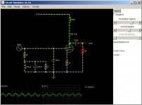
I have been trying to find a circuit simulator with tubes so I can then experiment and understand without bothering you here too much. Please see the attached picture. I did this using the java app. from Circuit Simulator Applet . However, there is no options to change the properties of triode in it, in fact there is no guide what this triode is doing except extremely high amplification. Otherwise I used all the specification from Thorsten's design including the grid bias of -0.1V.
Does anybody know about any such program that can model ECC88, 6H30 in this circuit? What about TubeCad? Does it has options to add and chose from wide array of passive and active components? Is it just a design tool or a complete simulator? I could not conclude that from its website.
Does anybody know about any such program that can model ECC88, 6H30 in this circuit? What about TubeCad? Does it has options to add and chose from wide array of passive and active components? Is it just a design tool or a complete simulator? I could not conclude that from its website.
Attachments
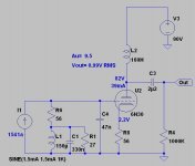
1541a with 6H30 Thorsten's buffer.
Output only 1V RMS!
Wow! euro21, that you so much
, you are the Man. Can you please share that you just ran the simulation on my insistence or you have actually built it?I have downloaded LTSpice and will be experimenting with it. Can you explain what does the SINE (1.5mA 1.5mA 1k) means at the bottom of the screen shot. My guess is 1k sine wave from 1.5mA current source?
Hi,
I have posted in the "digital line level" part of this forum a tube based I/V converter. We have successfully tested it with a TDA1543 and it sounds impressive (compared to my CD Player).
The input impedance is simed at 0.1Ω on the audio bandwidth (and more) and the output is 4.2Vpp with the TDA. We also simed a schematic for the TDA1541 adding the constraint it output pins must be at 0.000V.
Cheers
greg
Hi,
In practice and with real tubes you will struggle to keep the input (and thus the TDA1541 Output) correctly at 0V, unless you add a servo.
Additionally, the circuit you show uses large amounts of negative feedback to get the very low input impedance and it has several capacitors (including an electrolytic capacitor) in the feedback path.
It may a better choice to just use a decent Op-Amp (OPA637 would be my choice).
In the end it is down to personal preference of course.
If we use the 6F12 it may be a better choice to get a NOS ECF82/6U8 instead of the russian or chinese 6F12.
And in my view instead of trying to make the tube work in common grid mode, especially for the TDA1541, just use a Mu-Follower with a suitably scaled I/V Resistor (the ECF82 Mu Follower should manage a gain of near 40)...
As for using a 6N30, I fail to see the point. In the big scheme of things I have not found it to be a very good sounding valve. I know it is heavily hyped by some (especially high end companies that use them) and has gotten quite expensive, to a point where many good NOS Valves that sound much better cost way less.
There are still many underrated and undervalued NOS tubes around that would be a far better choice than the 6922/E88CC or 6N30, for example the E180F triode connected or the C3g triode connected are excellent. If the gain is too high, scale the Current/Voltage converter.
Ciao T
The input impedance is simed at 0.1Ω on the audio bandwidth (and more) and the output is 4.2Vpp with the TDA. We also simed a schematic for the TDA1541 adding the constraint it output pins must be at 0.000V.
In practice and with real tubes you will struggle to keep the input (and thus the TDA1541 Output) correctly at 0V, unless you add a servo.
Additionally, the circuit you show uses large amounts of negative feedback to get the very low input impedance and it has several capacitors (including an electrolytic capacitor) in the feedback path.
It may a better choice to just use a decent Op-Amp (OPA637 would be my choice).
In the end it is down to personal preference of course.
If we use the 6F12 it may be a better choice to get a NOS ECF82/6U8 instead of the russian or chinese 6F12.
And in my view instead of trying to make the tube work in common grid mode, especially for the TDA1541, just use a Mu-Follower with a suitably scaled I/V Resistor (the ECF82 Mu Follower should manage a gain of near 40)...
As for using a 6N30, I fail to see the point. In the big scheme of things I have not found it to be a very good sounding valve. I know it is heavily hyped by some (especially high end companies that use them) and has gotten quite expensive, to a point where many good NOS Valves that sound much better cost way less.
There are still many underrated and undervalued NOS tubes around that would be a far better choice than the 6922/E88CC or 6N30, for example the E180F triode connected or the C3g triode connected are excellent. If the gain is too high, scale the Current/Voltage converter.
Ciao T
In practice and with real tubes you will struggle to keep the input (and thus the TDA1541 Output) correctly at 0V, unless you add a servo.
Hi Thorsten,
This constraint has been simed using a basic opamp, the simulation showed 0.000V +5µV at the input.
Additionally, the circuit you show uses large amounts of negative feedback to get the very low input impedance and it has several capacitors (including an electrolytic capacitor) in the feedback path.
Still true, the delay group for the input is 5ms at 20Hz and 0ms @100Hz. The simulation showed this does not impact the ouptut though.
Well, the problem with the Op-Amp is that it uses a high negative feedback AND its gain dramatically decreases over the audio bandwidth making the input impedance to increase with frequency. To limit the effects of this variation, low I/V resistors are used which leads to add a pre-amp stage that creates its own distorsion. A pre-amp has of course a high output impedance that needs a buffer stage before we can output the signal to the power amplifier.It may a better choice to just use a decent Op-Amp (OPA637 would be my choice).
TDA + I/V is my home no-preamp
and I can say it sounds a way better than the wolfson DAC of the cambridge I use as CD player.In the end it is down to personal preference of course.
I do still agree, music is more important than electronics
Cheers
greg
Hi,
Simulations are powerful tools, however I have to find to a simulation tool that allows me to reliably predict the sonics of the circuit simulated.
I am less worried about the group delay and more about the non-linearity of that capacitor.
That depends on the precise Op-Amp and the precise circuit used.
If you use the OPA637 in the configuration shown by Scott Wurcer for the AD797 (which incidentally also makes sure that OPA637 which is not stable at gains below 5 remains stable) this is not a big issue. If you use an AD811 or LM6181 it is a non-issue.
Your common grid I/V stage also has distortion. It may be lower in absolute terms, however the use of negative feedback will invariably create a different distortion spectrum compared to a straightforward gain stage, likely that favour higher order products.
The original I/V & Tube gainstage at the start of this thread was designed to have a low enough output impedance (around 2.5KOhm) to not cause any major issues, unless the Power/Pre/Integrated Amplifiers input impedance is below 10KOhm. No buffer stage is used.
In my case I use the TDA1541 with a variation of the above I/V & Tube Stage (mine uses 6072A and hybrid FET current sources with a "Mu-Follower" output). I do have a preamp however, as my poweramps do not have volume controls.
Ciao T
This constraint has been simed using a basic opamp, the simulation showed 0.000V +5µV at the input.
Simulations are powerful tools, however I have to find to a simulation tool that allows me to reliably predict the sonics of the circuit simulated.
Still true, the delay group for the input is 5ms at 20Hz and 0ms @100Hz. The simulation showed this does not impact the ouptut though.
I am less worried about the group delay and more about the non-linearity of that capacitor.
Well, the problem with the Op-Amp is that it uses a high negative feedback AND its gain dramatically decreases over the audio bandwidth making the input impedance to increase with frequency.
That depends on the precise Op-Amp and the precise circuit used.
If you use the OPA637 in the configuration shown by Scott Wurcer for the AD797 (which incidentally also makes sure that OPA637 which is not stable at gains below 5 remains stable) this is not a big issue. If you use an AD811 or LM6181 it is a non-issue.
To limit the effects of this variation, low I/V resistors are used which leads to add a pre-amp stage that creates its own distorsion.
Your common grid I/V stage also has distortion. It may be lower in absolute terms, however the use of negative feedback will invariably create a different distortion spectrum compared to a straightforward gain stage, likely that favour higher order products.
A pre-amp has of course a high output impedance that needs a buffer stage before we can output the signal to the power amplifier.
The original I/V & Tube gainstage at the start of this thread was designed to have a low enough output impedance (around 2.5KOhm) to not cause any major issues, unless the Power/Pre/Integrated Amplifiers input impedance is below 10KOhm. No buffer stage is used.
TDA + I/V is my home no-preamp
In my case I use the TDA1541 with a variation of the above I/V & Tube Stage (mine uses 6072A and hybrid FET current sources with a "Mu-Follower" output). I do have a preamp however, as my poweramps do not have volume controls.
Ciao T
Hi,
Non, you cannot use it. Due to the minimal biasing of the ECC88 (only -0.2V fixed bias from DAC's output current offset) most other tubes will simply not work at all.
You can add cathode biasing, but that raises the anode impedance etc., it is just opening a major can of wriggely worms...
There is no later version of this in the public domain.
The closest a "2011" might come is a commercial "DIY Module" tube stage I designed a few years back. I would not say that it is worse or better, it is different and was designed to be very compact so it can be fitted as after-market modification to existing CD and DVD Players...
I would post links to this, but as I'm always accused to only post to promote my wares I shall not.
Ciao T
1) What changes I have to do in this Thorsten circuit if I want to try 6H30 instead of ECC88?
Non, you cannot use it. Due to the minimal biasing of the ECC88 (only -0.2V fixed bias from DAC's output current offset) most other tubes will simply not work at all.
You can add cathode biasing, but that raises the anode impedance etc., it is just opening a major can of wriggely worms...
2) Is this the last version by Thorsten or is there any upgraded version? I mean this is from 2005, any 2011 version?
There is no later version of this in the public domain.
The closest a "2011" might come is a commercial "DIY Module" tube stage I designed a few years back. I would not say that it is worse or better, it is different and was designed to be very compact so it can be fitted as after-market modification to existing CD and DVD Players...
I would post links to this, but as I'm always accused to only post to promote my wares I shall not.
Ciao T
- Status
- This old topic is closed. If you want to reopen this topic, contact a moderator using the "Report Post" button.
- Home
- Amplifiers
- Tubes / Valves
- Thorsten's tube Stage for TDA1541A