Hey Guys,
I'm working on some SPICE models for a tube amp design. I've had a lot of luck in finding specs and models for tubes. But, finding similar information for transformers is proving to be more difficult to find.
I've got some test subjects (UTC LS-55) and, I think I have all of the necessary test equipment:
Thanks!
-Brian
I'm working on some SPICE models for a tube amp design. I've had a lot of luck in finding specs and models for tubes. But, finding similar information for transformers is proving to be more difficult to find.
I've got some test subjects (UTC LS-55) and, I think I have all of the necessary test equipment:
- KH 5920 function generator (nano to megahertz)
- Instek digital o-scope (>20hz to gigahertz)
- HP 4276A LCZ (100hz to 20kHz)
Thanks!
-Brian
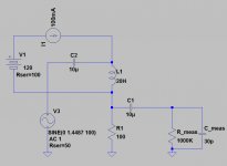
Build a series resonance circuit with the transformer, a known capacitor and a adjustable resistor (10k to 100k). Feed the AC-voltage across this circuit.
If you have a guess about the inductance of the (primary) transformer, select the value of the capacitor so that the resonance frequency is relatively low (100 Hz to 500 Hz). Then observe the voltage across the transformer and the capacitor with your scope and by adjusting the frequency of your generator you can find the notch frequency.
Then you simply calculate the inductance.
You can get the notch more sharp if the series resistance is higher.
You measure the main inductance with open secondary, and the stray inductance with shorted secondary. Measuring at low frequency (100 Hz or 120 Hz) is usually sufficient.
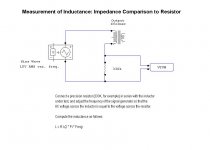
Using the resonant method the formula is:
1
------------------ = f
2 pi sqrroot(LC)
So
L = 1
--------------------------
4 pi squared f squared C
1
------------------ = f
2 pi sqrroot(LC)
So
L = 1
--------------------------
4 pi squared f squared C
Of course for accurate measurement of a SE OPT you would need to load the primary with an appropriate DC current me thinks.
The original Williamson articles provided a simple benchmarking technique for OT primary inductance comparison, given that inductance is quite dependant on excitation level.
I'm not sure if the transformer models include basic inductance versus excitation variation modelling.
I'm not sure if the transformer models include basic inductance versus excitation variation modelling.
What's the reason for wanting to measure o/p tranny inductance it ? On E&I types, inductance is never specified as the miniscule airgap between the laminations when screwed up can wildly alter the figures. A toroid with continuous strip is far more predictable.
richy
richy
- Status
- Not open for further replies.
- Home
- Amplifiers
- Tubes / Valves
- What is the proper way to measure transformer inductance?