Hi
Thanks for reply , unfortunately I am at the stage where is little to late to make so drastic changes , amp is already assembled and working .
I need to get best out of it ' what's your take on series resistor in line with choke in clc filter?
Have you ever used interstage transformers , I am not entirely convinced about using secondaries damping resistors.
Regards
Slav
Hi
I have done some web research and 1660 is apparently better working (sounding) if secondaries are not dampened by resistance , your comments please.
original diagram shows no grid leak resistor , I pointed this out and been told that it would cause high frequency resonance blocking, what about that?
Regards
So you found out. Let the 1660 ring, it only plays music when the secondaries are not loaded.
About cathode it can not be left unbypassed as you will get gross lowend loss. The alternative to bypassing is using LED bias.
Not talking about this particular case, but speaking generally I've tried bypassing cathode and leaving it unbypassed with a 46 into a Hammond 126C. I preferred the unbypassed cathode. A polypropylene bypass flattened out the harmonic subtleties of strings and woodwind slightly but quite perceptibly, an electrolytic was worse still and sucked the life out of the music. Bass was OK without the bypass.
In the case above the inductance of the 126C is 106H and the anode resistance of the 46 is around 2.5K. I suspect that it's this relationship which determines whether a bypass is better or worse.
Andy
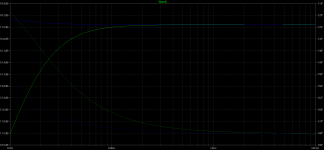
I'm also failing to understand the graph - I interpret that the heavy green line is supposed to represent the bass falling off with an unbypassed resistor, and I'm assuming the blue line is a flat response when bypassed. But I don't see where phase response comes into this. And in any case, what's happening in the bottom frequencies doesn't tell us what the overall sound quality over the whole harmonic spectrum is going to be bypassed and unbypassed.
andy
andy
Hi
would ccs be any good in this circuit , there is 1.6V on cathode resistor only
Everytime (pp El34 ; Adagio DAC) I tried cathode bypass I wasn't impressed by the sound and ended up with cathode resistor itself .
Regards
I'm like you - didn't like the sound of cathode bypasses. I don't particularly like the sound of active devices in CCSs and active loads - tried IXYS parts in both. I ended up with plate chokes instead of active devices, and negative rails with differential pairs. With SE stages I prefer filament bias for DHTs - no cathode bypass.
Andy
Power Supply question
Hi
I have another question ,
as second capacitor provides energy for output tubes for at least 80% of the time , how to calculate their capacitance ?
For instance I use 47uF (polypropylen) - 8H - 470uF filter , it means second cap is charged to ~470V and stores approx. 53 Joules (50W/1second)
My amplifier has 2 separated supplies to power booth channels ( one channel consumes 475Vx0.045Ax2 = 43W in Push Pull operation) , question is if 470uF is enough or should be bigger ,but by how much - what's the rule?
Another question , if I need to increase capacitance , is there anything bad ( from performance point of view) in parallel connection of another cap?
And one more question , final decoupling capacitor , I have chosen 100uF preceded by 27k resistor , I have read that too big cap in preamplifier circuit might cause LF degradation , how to choose value of this cap ,should I simply follow :
C=1/2*Pi*R for cut-off frequency 1Hz , so :
C=1/2*Pi*27000=5.8uF , and use 8-10uF?
Regards
Hi
I have increased capacitance in my PSU , anyway, it made sound little better , but... there is still bit of harshness in treble.I was wondering if grid stopper in 2C51 circuit is little too low -R390 and it causes instability of the higher frequency range. Anyone uses 2C51. what value works best in your application.
And once again I ask about grid-leak resistor , use or not , whats your oppinion
Regards
Back to basics,
KT88 is biased to -55V on the grid , 475V on anode , under 50mA current.
It means I need 110V peak-peak voltage swing ( +55V - -55V) , or 55*0.707= 38.9 VRMS, my interstage is connected in step down configuration 4:2.25+2.25 ,
which gives 38.9 /(2.25/4)= 61 VRMS needed on primary
amplification factor for 2C51 under 135-140V plate voltage and 7.2mA is 35 it meams I would need 1.9 VRMS input voltage ong grid
2c51 is biased to approx. -1.5V , it has no chance to work properly , am I right?
what if I use LL1660 in ALT V configuration , step down ratio is only 2.25:2+2 , once again 38.9 / (2,25/2) = 34.6 VRMS and I need only 1VRMS on the grid of 2C51 to give me full voltage swing on the grid of KT88.
Only downside is ALT V connection requires source impedance not more than 3.5K while 2C51 under described conditions has plate resistance approx 6.5k
AltV connection also lowers inductance of primary winding which acts as a anode choke. Anyone tried this
Am i right with my calculation?
- Status
- This old topic is closed. If you want to reopen this topic, contact a moderator using the "Report Post" button.
- Home
- Amplifiers
- Tubes / Valves
- Best design for Lundahl LL1679/PP