Hello, I'd like to accurately check the bias on my 6L6 amp. Is it more accurate to read the current between pin 8 and ground with an ammeter or to use measure the voltage across 1 ohm 1% shunt resistor between pin 8 and ground. I am concerned about using the ammeter method in case the fuse blows or a lead gets unplugged leading to an open circuit whereas the shunt resistor would not break the circuit. Any help would be appreciated.
A 1 ohm resistor will be invisible to the circuit, but it makes taking current readings simple. Imv = 1ma. You could insert an ammeter in series with the cathode, but I don;t see any real advantage. Use a 1% resistor and your readings will reflect that, within the accuracy of your meter.
If you have a series ammeter instead of the 1 ohm resistor, if it opens or gets disconnected, then the tube will stop conducting current. No current path. Won;t hurt it, some amps use that method to create a standby switch.
But there is a larger question. You are concerned over which one of these ways to measure the same thing is "most accurate," but cathode current inscludes the screen current of the tube. it is not just another place to measure plate current.
Now we use this method all the time, it is convenient, and frankly accurate enough. But we allow a few extra milliamps for screen current. Bias is not really rocket surgery, a milliamp either way is not going to make a huge change.
SO to get it "accurate," you will need to allow for screen current. You can meausre cathode current any way you like, then also determine screen current and subtract it. Assuming you have screen grid resistors, you can measure their resistance and the voltage across them, and simply calculate screen current.
Or you can ditch the cathode route completely and insert an ammeter in the plate lead. The 1 ohm trick would work there too, but the resistor would not be at ground potential, it would be sitting at B+, so less safe.
Any work inside a tube amp is not "safe," so exercising due caution, this method would not be a threat to you.
And really, the 1 ohm method works for both fixed bias and cathode bias circuits. If you have for example a 250 ohm cathode resistor for cathode bias, adding a 1 ohm resistor in series with that won;t change the bias to the tube appreciably. 0.4% in fact.
Most practical and sufficiently accurate method is to measure the voltage across the cathode resistor. In case of fixed bias the resistor can be anything between 1 to 10 ohms.
To use ammeter at the cathode is quite bulky method, but not dangerous if the circuit gets open. Then the current flow in the tube simply cuts off.
But if the ammeter is at the anode and the circuit gets open, then the screen current jumps to huge value and the screen grid can get damaged.
I am concerned about using the ammeter method in case the fuse blows or a lead gets unplugged leading to an open circuit whereas the shunt resistor would not break the circuit.
To use ammeter at the cathode is quite bulky method, but not dangerous if the circuit gets open. Then the current flow in the tube simply cuts off.
But if the ammeter is at the anode and the circuit gets open, then the screen current jumps to huge value and the screen grid can get damaged.
Thanks Enzo and artosalo. What I really want to do is build a bias probe for quick and easy measurements but there are different ones that claim better accuracy. Some claim the ones that break the circuit for ammeter use are less accurate because of lead length and meter resistance. They were also the ones that claimed damage could happen if the circuit opened. I'll probably go the route of the shunt resistor . I have the parts so I just wanted some advise on the best way to check it. I guess it's important to use a 1% tolerance resistor too. Hopefully a 1 watt will be ok because it would fit inside the socket better that I'm going to use. I'm using this on a 6L6 guitar amp . I really don't think the readings have to be super accurate but a fairly accurate reading would be nice. The design I'm copying is a Weber bias rite.
Some claim the ones that break the circuit for ammeter use are less accurate because of lead length and meter resistance.
This is fully theoretical and does have nothing to do with practical life of tube amplifiers.
You could add 10 ohms (my preferred size) at both cathodes and connect a wire from this resistor to some connector (5 pin DIN etc.) at the rear side of the amplifier.
Then you can quickly and easily check the bias without opening the case of the amplifier.
They were also the ones that claimed damage could happen if the circuit opened.
Only if installed at the anode. If installed at the cathode, no damage can happen.
Hopefully a 1 watt will be ok because it would fit inside the socket better that I'm going to use.
Even a 10 ohms/ 0,6 W resistor is sufficient. the power dissipated at the resistor is below 30 mW.
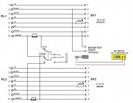
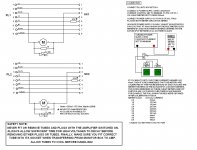
There is really no need to be super critical about bias setting, just set the bias controls for the recommended current e.g. 35mA using whatever method you choose for actual measurement. Assuming we are talking about a push-pull output stage, the fact is that after doing this, you might need to slightly adjust the bias for one of the output tubes either up or down for minimum supply ripple on the speaker output. You would need the proper test gear to see this and it ensures that the currents in the transformer primary windings are equal but opposite and thus cancelling themselves out. Most people would probably not bother doing this, perhaps rightly so, as the chances of miss-balance causing any saturation to the transformer core are pretty minimalistic! One unit you could construct is attached, using fly leads with plugs to match the tube holders in the Amplifier, you simply move the tubes from the amp to the unit. You can then plug a Multimeter into the unit, select which tube you want to measure and press the associated button. The button switches allow you to switch in the Multimeter without interrupting the tubes cathode circuit. This is not a problem in itself but without this method one is likely to make a very loud POP in your speakers and is probably the reason why others warn of this method.
Of course you could spend a lot of $$$ on a so called biasing probe but they are nothing more than the attached circuit. The unit was constructed for EL34/6CA7 tubes and other tubes may require circuit changes to suit. The resistors are needed to act as Grid Stoppers, without them you could get oscillation. If the values given do not prevent this then up them to something like 1k, always fitting them as close as possible to the tube bases fitted to the unit.
Attached is also a drawing of a system using twin meters, useful for watching both tubes at once.
Les
Attachments
As far as I am concerned PLATE current is not CATHODE current..... I don't buy into all the rationalization of measuring cathode current....mainly because tubes can pull anywhere from 4mA to 12mA at idle on the screen....and your question was about most accurate method...SIMPLE, just put an ammeter in series with the plate and your done with it....I make my own octal plug to put between the chassis socket and tube....Pin 3 is interupted and sent to my FLUKE 87 in the DC mA setting so it is series with the plate pin...Biasing with signal in the amp is also imortant..since it's nice to know whats going on with the waveform and distortions...
Best Regards
Chris
Best Regards
Chris
Hi Chris, you are quite correct, the cathode current is a combination of both screen and plate currents. Most amplifier manufacturers however state what the cathode current should be, normally using the voltage drop across a monitor resistor placed in the cathode circuit. I guess it establishes some kind of datum and being of low potential reduces the safety risk. Glad to see you also prefer to use an external monitor box, which could of course be extended to allow both plate and screen voltages and currents to be easily measured.
Regards, Les
Regards, Les
Another point about measuring cathode current from the cathode resistor method..
If I were to only measure the cathode current, then I would subtract about 4 or 5 mA for good measure to account for screen current on most 6L6 and EL34 valves...
Or I just measure the voltage drop across the screen resistor and figure the current and subtract that from cathode current..
The biggest headache is not the DC current matching but making sure the gm is matched mostly in HiFi gear...
Chris
thanks everyone, I think I'll just build the bias probe with the resistor between pin 8 and be done with it. I should've asked initially which of the two methods is more accurate rather than asking what the most accurate way is. I'm basically just trying to make sure my guitar amp is in the ball park so I don't damage some new TAD's I'm looking to buy. The hard part will be trying to figure out what control voltage I need to set the tube at around 35ma. It's fixed and uses zener diodes to set the voltage so I may have to do a hit or miss with different value zener's.
Last edited:
- Status
- This old topic is closed. If you want to reopen this topic, contact a moderator using the "Report Post" button.
- Home
- Amplifiers
- Tubes / Valves
- Most Accurate Bias Testing Method