Is there a way to know how much power can be put through a particular output transformer? I know that size and weight are good indicators. But is there a formula or a test that can be used to rate a particular transformer's power rating?
Thanks for any help you could provide.
Thanks for any help you could provide.
Last edited:
I presume you imply push-pull.
Becareful with the weight reasoning: large core area can imply extended LF range for a given size winding wire and modest power, the original 20W Mullard design stipulated a large core 50x150x125mm which bears little relationship with power throughput but can handle flat response below 10Hz. Generally, a High inductance implies good LF response for a given Bmax (excitation flux), however can also be achieved with large AE (core area) and /or lesser number of turns; this last bit is ideal for the HF response and the designers biggest headache is maintaining the upper response with minimum losses.
Taking the Mullard size example, an output transformer with LF cutoff at 40Hz for the same power would be designed perhaps 2/3rd smaller for the same power throughput.
A specifically sized output transformer designed for 20Hz full power cutoff would be half the size at 40Hz for the same power. It makes sense that E guitar string is around 39Hz and designing the transformer to this frequency makes everything more portable. YOu wanna to go to a lower frequency using tha same transformer, then reduce the power vs frequency to fit the classic formula:
Bmax = Vin/(4.44xAexFxN) If one knows the original design Freq, with both Ae & N fixed, simply substitute the classic equation to find F for a given core size. Ae as e-4 metre sqr'd.
In the pic, both two p-p output transformers from the same manufacturer have windings rated for the same power, both 150W. However the larger one has cutoff designed at 15Hz and the other 20Hz. The copper wire OD on the larger core (hence larger bobbin) has a larger diameter wire OD to reduce the DC resistance which is desirable to keep THD and winding heating losses down. Problem: the larger core with more copper area has a higher leakage inductance & capacitance hence, the smaller core can often out-perform on the HF response; 75Khz versus 50Khz. This the reason that output transformers are critical in design and a pain to optimise as they get bigger.
One will never get far with output transformer dynamics without stretching one's knowledge of physics and importantly magnetics.
richy
Attachments

Assuming push-pull. not single-ended.
First, you need to determine minimum cross-section area based on lowest frequency (almost always taken 20 Hz) and output power required. This is quite simple.
Flux Density in Gauss B = 10^8 * sqrt(Power * Primary Impedance) / (4.44 * Area * Stacking Factor * Primary # of Turns * Lowest Frequency)
Assuming maximum number of primary turns 3500, lowest frequency 20 Hz, stacking factor 0.92 and maximum flux density B = 12500G and B = 14000G for EI and double C core respectively, we will get:
Area in sm^2 = 10^8 * sqrt(Power * Primary Impedance) / (B * 4.44 * 0.92 * 3500 * 20)
Thus, for example, transformer 50W, 5000 Ohm primary impedance, you will need at least 13.99 sm^2 (EI core) or 12.49 sm^2 (double C core). However, make sure that core have enough window size to accommodate required turns of both primary and secondary.
Last edited:
Cool Awesome what we learn here! The lowest note on a standard tuned giitar is about 80Hz, (not 40). Which explains why the OT on Fender's 40W guitar amp is smaller than Hammond's 1620, a 20watt HiFi OT. The inductance on a Deluxe OT was only 4H, and it is used with 6L6, the turns ratio is 4k:8. Even so it sound great for it's intended use.
 Post #3 by LinuksGuru edited to correct core area values cited as example with information he subsequently provided.
Cool Awesome what we learn here! The lowest note on a standard tuned giitar is about 80Hz, (not 40). Which explains why the OT on Fender's 40W guitar amp is smaller than Hammond's 1620, a 20watt HiFi OT. The inductance on a Deluxe OT was only 4H, and it is used with 6L6, the turns ratio is 4k:8. Even so it sound great for it's intended use.
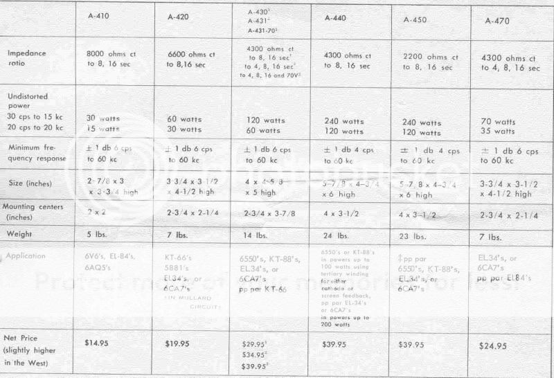
if you look at dynaco transformer spec sheets, you will find that there are several power ratings, always with a bandwidth attached to power spec, please look at the third row:
Good physics stuff this is:
Note:-Remember these aren't mains transformers so for min thd for HiFi the max core flux (Bmax) is much lower for the reasons outlined below.
Intermodulation and harmonic distortion results from the non-linearity between the magnetising current and the magnetic field in the transformer. Everyone who meddles with the physics should know that. These curve dysfunctions can be reduced by keeping
Bmax below a certain value around 7000G (0.7T) for output transformers using standard transformer sheet. So that's the reason one should NOT compare mains and output transformers, like for like sizes !
On my 4string You'll find me playing E at 41 + odd Hz and in the past all MI transformer designers calculated at that frequency.
richy
Bass guitar tuning - Wikipedia, the free encyclopedia
Good physics stuff this is:
On my 4string You'll find me playing E at 41 + odd Hz and in the past all MI transformer designers calculated at that frequency.
richy
Ah, you were talking 'bout bass-guitar, I thought you meant guitar-guitar.
I think MI OTs for guitar-guitar calculate around 80Hz as the lowest usable frequency, at least from just looking at the size of a lot of 40-50watt OPT on guitar amps.
Intermodulation and harmonic distortion results from the non-linearity between the magnetising current and the magnetic field in the transformer. Everyone who meddles with the physics should know that. These curve dysfunctions can be reduced by keeping
Bmax below a certain value around 7000G (0.7T) for output transformers using standard transformer sheet. So that's the reason one should NOT compare mains and output transformers, like for like sizes !
7000G is a way too low for CRGO/GOSS, 12500-:-14000 G will work fine with modern M4. Low or medium power (~25W) transformer with low flux is more or less OK, but 60-80W unit will be, simply put, too big, and suffer from another problems like high stray capacitance, or poor performance at low signal level.
Rich is right not to compare size of main 127/220V and output transformers, without precise math it doesn't make any sense.
Apart from minimum cross-section area, core must have window large enough to accommodate windings with much higher number of turns then those usually found on power line units.
PS. Once I have seen monster 6W output transformer weighting 40Kg (88 lbs) made in Russia, but IMHO this is some kind of schizophrenic design.
Even of this is an old thread, may I ask a simple question:
I am using this opt with 4 el34:
http://www.amplimo.nl/images/downloads/ds vdv/vdv3070.pdf
...in UL.
Actually I would like to optimize my amp to drive as much in class a as possible, so more current, lower voltage, less efficiency, but by purpose and design.
Can I do that ? Or is there as well not just a power limit, but as well a current limit ?
Best Regards
Frank
7000G is a way too low for CRGO/GOSS, 12500-:-14000 G will work fine with modern M4. Low or medium power (~25W) transformer with low flux is more or less OK, but 60-80W unit will be, simply put, too big, and suffer from another problems like high stray capacitance, or poor performance at low signal level.
Okay, that's your side; but I look at the core size # throughput power versus F3 distortion content of 1.4% at the lowest design frequency, which stabled designers work via Steinmetz's law. It seems now flouted with fantastic sound claims maybe for MI but certainly not for HiFi. This isn't high physics but follows a good calculation of iron-created-hysteresis harmonics on amp designs NOT using global nfb, to have a generous designed iron size to clean up' the harmonic spectrum. This explains, the designers of the Mullard 5-20 used a large output transformer for it's relatively low output power, despite that circuit using a high amount of 30dB global feedback to get distortion issues down to mere 0.00? % to create sales in 1960. However, as most seasoned SE Amper's using circuits with no gfb probably know, that selecting output transformers is the most choosy object that can effect sound quality with it's exotics such as silver wire and other enhancements. (tricky subject as everyone knows)
richy
Last edited:
If this is a toroid I think a lot of current might not be a good idea? From what I understand toroid OPTs tend to saturate. I would contact Vanderveen himself to get your answer. Menno van der Veen, audio electronic research & consultancy
If this is a toroid I think a lot of current might not be a good idea? From what I understand toroid OPTs tend to saturate. I would contact Vanderveen himself to get your answer. Menno van der Veen, audio electronic research & consultancy
Unbalanced current is not a good idea in Torroids. In a push pull transformer, the current in each side of center tap cancels one another out, so as long as the currents are balanced, there is no problem.
I've been building tube amps for about fifteen years now and one thing I've learned is that transformers are not very flexible in application. And that if you try to force them out of their comfort zone you always have a decrease in performance. Toroidal output transformers can perform well when used as intended but they have a narrow window in practice. If you increase current and decrease voltage you will change the output impedance of the tubes and then the specs are out the window. If you want to build a single ended or class A PP amp I would sell the transformers you have and buy the transformers you need. Building amps is too time consuming and costly to take chances.
I asked by now Menno and got an answer:
"Hi Frank
I am already running for a long period the UL40S2 at higher currents
with 6550/KT120/KT150. No problems.
A short hint:
1) V-B+ = 350 V in the UL40
2) Anode dissipation: Pmax = 40 Watts (6550) or 60 W (KT120)
3) Then Io-max = 40/350 = 115 mA (6550) or 60/350 = 171 mA (KT120)
4) I would not bias for the maximum of the tube because of the
life-span shortening of the tube
5) My advise: 80 mA max for 6550 and 120 mA max for KT120
6) under these conditions, the power transformer will get somewhat
hotter, but not alarming
7) The OPT VDV-6040 is designed to withstand these higher currents.
I would say, go for it. I have done it without any problems.
"
- Status
- Not open for further replies.
- Home
- Amplifiers
- Tubes / Valves
- output transformer power rating