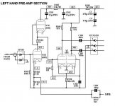
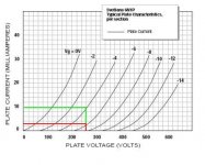
Looking at the voltages around the input stages, the voltage drop across the 1k resistor would suggest that a current of 3mA is flowing through the circuit. The data curves for a 250V Plate supply at 3mA would suggest that the 6N1 is not being operated at its most linear part (Red line on graph). Does the Team think that the current needs to be increased to say 10mA as shown by the Green line to improve its operating point? Perhaps I have this all figured out wrong, after all the amp does sound nice as is, and the fear of adjusting may push the operating conditions of the phase splitter into a bad area.
Does anyone have any suggestions for the improvement of these stages?
I have a feeling that any answers to these questions would be looked upon with great interest by Yaqin owners.
Les
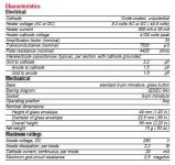
P.S. The maximum plate voltage of 250V for the 6N1 suggests it is being pushed a bit in the Yaqin circuit :-(
I also realise I made a mistake in that the plate voltage of the first amplifying element is 121V and not 250V, but the curve is still very bent at this point.
Does anyone have any suggestions for the improvement of these stages?
I have a feeling that any answers to these questions would be looked upon with great interest by Yaqin owners.
Les
P.S. The maximum plate voltage of 250V for the 6N1 suggests it is being pushed a bit in the Yaqin circuit :-(
I also realise I made a mistake in that the plate voltage of the first amplifying element is 121V and not 250V, but the curve is still very bent at this point.
Attachments
Last edited:
Obviously some component values would have to change. I have tried to remodel based on increasing the current from 3mA to 10mA but something tells me things are not as simple as this. Does anyone have the ability to perhaps Spice the circuit or advise on component changes?
Attachments
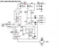
with 120V plate to cathode at 10mA the Vgk would be around 0V...not good. So maybe 5mA is a better target... to achieve it I would go with a 220R for R104 and 180R for R102, 180R for R102 combined with the existing 47R would be 227R, a bit more than 220R on the top, but still more or less balanced. Or go for 170R for R102, but 220R and 180R are standard values!
Thanks for your input Erik, what was I thinking? R104 should be 330R in my marked up attachment. Funny how the brain gets disengaged when you are sat at the keyboard ") . I presume the 124v must be preserved at the grid of the phase splitter so that prompted me to adjust R105. Looks like some more experimenting is due when my amp gets its annual look over.
. I presume the 124v must be preserved at the grid of the phase splitter so that prompted me to adjust R105. Looks like some more experimenting is due when my amp gets its annual look over.
Les
. I presume the 124v must be preserved at the grid of the phase splitter so that prompted me to adjust R105. Looks like some more experimenting is due when my amp gets its annual look over.Les
Yes, you are right: the 120V should be preserved for the phase splitter. Looking again at the schematic I see that the upper tube has about 180V plate - cathode, while the lower has 120V...Using similar valued cathode resistors, as I suggested before, will bring these values to 150V and 150V = no good. Therefore I think your values are better (with 330R instead of 3k3, of course)... and experimenting is never a bad idea
- Status
- This old topic is closed. If you want to reopen this topic, contact a moderator using the "Report Post" button.
- Home
- Amplifiers
- Tubes / Valves
- Yaqin MC10L Question for the Guru's