Hi. I have a tube amplifier to repair. The problem is with the High voltage supply, there is no HV...
The rectifier tube is an EZ81.
I opened the amp and came across a strange HV section connection. The power transformer has no center tap for the tube rectifier (as I'm used to) but use a pair of silicone diodes to GND (1N4007) to simulate a full rectifier bridge (half tube and half solid-state). Both diodes were dead. I replaced the diodes (cathode to the HV transfo wires, both anode shorted to gnd), and tested the EZ81. It has good emission on the tube tester.
I connected the EZ81 and the problem is the tube rectifier is becoming really hot and glows a nice red cherry color (nice and frightening...). There is no HV produces and I suspect the SS diodes short the tube to gnd.
Any idea, suggestion? Is the problem the tube rectifier? Should that kind of circuit been working in the first place (it looks fine in theory). Is it a safe practice (I guest not)?
Please help.
A strange configuration for sure. I would make certain that each of the SS diodes is bypassed by a suitable cap to take care of any transients as the power transformer is turned off. Normally, the first filter cap would fulfill that duty, but with half tube, half SS, the possibility for damage is pretty high. The circuit should work. If the diodes are good and correctly installed, and there are no shorts in the B+ distribution system, then the tube should work properly as well -- unless one section of it is damaged as well.
Dave
Dave
I think this is common 'hybrid' circuit, half SS, half tube, to setup a full wave bridge rectifier without CT...
But the problem why the diodes keep blowing is quite strange...
Have you check whether the circuit are OK? Disconnect the PSU from the circuit to check whether you have some short which sucks the current above normal...
Thanks.
But the problem why the diodes keep blowing is quite strange...
Have you check whether the circuit are OK? Disconnect the PSU from the circuit to check whether you have some short which sucks the current above normal...
Thanks.
Nothing wrong with a hybrid graetz bridge. It is also safe. But I would add 2 or even three ss diodes in series per hv wire. Just to be on the safe side. As you can see the previous ones died prematurely.Any idea, suggestion? Is the problem the tube rectifier? Should that kind of circuit been working in the first place (it looks fine in theory). Is it a safe practice (I guest not)?
What is the value of the first capacitor after the EZ81. And how much current is being drawn by the circuit.
Did you check the pinout and connections? Maybe the previous owner tried to fix it himself. And instead of replacing the ss diodes he rewired the rectifier tube?
It was bought by my customer directly from the guy that built it, so I guest it is as built. Yes, the pinout is ok.
This is the kind of safety recommandation I was looking for. I'll certainly install the RC and some more diodes.
This is what I think that the tube is defective. I'll order a replacement tube and check.
And thanks Bas for the name of the circuit. This I was looking for too. Here a schematic of this connection, for those curious as me")
It is connected exactly like this in the amp, so the diode polarity is correct too...
This is the kind of safety recommandation I was looking for. I'll certainly install the RC and some more diodes.
This is what I think that the tube is defective. I'll order a replacement tube and check.
And thanks Bas for the name of the circuit. This I was looking for too. Here a schematic of this connection, for those curious as me
It is connected exactly like this in the amp, so the diode polarity is correct too...
Attachments
EZ81 limits are 100mA DC at 450V AC (160mA at 250V), 50uF reservoir cap, and series resistance of at least 310 ohms (150ohms at 250V). You can exceed one of these provided you keep well below the limits on the others.
100uF breaks one limit, so are you on the safe side of the others?
BTW your diagram is wrong. EZ81 has separate connections for heater and cathode.
100uF breaks one limit, so are you on the safe side of the others?
BTW your diagram is wrong. EZ81 has separate connections for heater and cathode.
You stated that the EZ81 glows red when you turn it on and you have no B+ voltage. I have had the same thing one time with a 5AR4, it turned out that the filter capacitor had shorted out which caused a short circuit.
Based on my previous experience I strongly recommend you to check the power supply for any short circuits
Based on my previous experience I strongly recommend you to check the power supply for any short circuits
My friend first of all disconnect the amplifier from the power supply and try once more. Then if you still have the same I would suspect the 1st servoir capacitor which i would suggest to change it with a 47uf MAXIMUM. In case the problem is the EZ81 tube just try to replace it with two silicon diodes just for checking. In case you try this disconnect the rest of the circuit because the HV will be a bit higher than before.
Chris
Chris
I suspect you should replace the EZ81 before going any further.. I would also add 1M/1W flame proof metal oxide resistors and 0.01uF/1kV ceramic caps across each 1N4007..
Old thread I know, but the search function on this site is amazing. I'm in the process of building an amp using a 6BY5 rectifier with an Antek toroid PT that has no center tap for the filament winding. Thanks very much for the tip.
Last edited:
I hate to hijack a thread, but I don't want to start one just for this question.
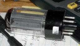
Can anyone identify this full wave rectifier?
It has the same pin out as a 6X5 or 6ZY5, but the plates seem a bit large compared to the 6X5s I have. One can see all the way through the tube between the plates. There are "T" shaped heat fins that are about 1" across the top of the T and 1/4" perpendicular to it.
Tks.
Attachments
- Status
- This old topic is closed. If you want to reopen this topic, contact a moderator using the "Report Post" button.
- Home
- Amplifiers
- Tubes / Valves
- Tube Rectifier with transformer without Center tap