I'm currently thinking to modify my old tube guitar amp (Guyatone GA-330-D). It has a (silicon) diode rectifier. I want to change, using tube rectifier 6X4.
The Transformator has no center tap. As mentioned by Algar_emmi I can use two diodes and R1. Atached the schematic I would like to use.
Which R1 should I use? 1M 2 Watt?
The Transformator has no center tap. As mentioned by Algar_emmi I can use two diodes and R1. Atached the schematic I would like to use.
Which R1 should I use? 1M 2 Watt?
Mod. old Guitar amp
I'm currently thinking to modify my old tube gutar amp from Guyatone (GA-330-D). It has a (silicon) diode (may be 1N4007).
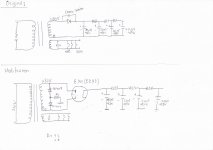
I wanto change it to tube rectifier using 6X4 (EZ 80) but has no center tap, only 0-280. Can I put two 1N4007 and a R1 to make a center tap? Should I take R1= 1M 2 watt? Is it safe and produce a "typical tube rectifier sound"? Attached the schematic I planed to use.
Currently, If I play using overdrive pedal after about 10 minutes the make a dub....dub.. for a millisecond. It disturbes me somehow and the chassis getting hot. I heard that it could be from the old elko in tht power section (Multisection Elko:40µ, 20µ, 20µ, 20µ). Is it right?
I'm currently thinking to modify my old tube gutar amp from Guyatone (GA-330-D). It has a (silicon) diode (may be 1N4007).
I wanto change it to tube rectifier using 6X4 (EZ 80) but has no center tap, only 0-280. Can I put two 1N4007 and a R1 to make a center tap? Should I take R1= 1M 2 watt? Is it safe and produce a "typical tube rectifier sound"? Attached the schematic I planed to use.
Currently, If I play using overdrive pedal after about 10 minutes the make a dub....dub.. for a millisecond. It disturbes me somehow and the chassis getting hot. I heard that it could be from the old elko in tht power section (Multisection Elko:40µ, 20µ, 20µ, 20µ). Is it right?
Attachments
I'm currently thinking to modify my old tube gutar amp from Guyatone (GA-330-D). It has a (silicon) diode (may be 1N4007).
I wanto change it to tube rectifier using 6X4 (EZ 80) but has no center tap, only 0-280. Can I put two 1N4007 and a R1 to make a center tap? Should I take R1= 1M 2 watt? Is it safe and produce a "typical tube rectifier sound"? Attached the schematic I planed to use.
Currently, If I play using overdrive pedal after about 10 minutes the make a dub....dub.. for a millisecond. It disturbes me somehow and the chassis getting hot. I heard that it could be from the old elko in tht power section (Multisection Elko:40µ, 20µ, 20µ, 20µ). Is it right?
I don´t now how much current you´ll draw through the tube but 40uF is max and if you stay below 70mA it´ll work.
Measure the resistance of the PT´s HV winding and add resistors in series to get high enough series resistance.
Put the resistors right in on the rectifier tube one in each anode.
In deed 60 mAI don´t now how much current you´ll draw through the tube but 40uF is max and if you stay below 70mA it´ll work.
It sounds a bit different than the schematic I have attached before. Could you please to give me the schematic?Measure the resistance of the PT´s HV winding and add resistors in series to get high enough series resistance.
Put the resistors right in on the rectifier tube one in each anode.
I wish people would remember - no matter whether using tube or sand rectification, it is better practice to have relatively small "first reservoirs". Though not much specified these days, even 10µF to 22µF are great high-voltage values. They're just so much easiier on the rectifiers, no matter what they are. In these "3 stage" filtering schemes, it makes more sense to double up on the downwind caps. And, to prefer inductors with snubber bypass resistors over just a string of resistors. More voltage delivered at every current requirement. Sweet.
But people keep thinking to use large caps up front.
I think this is because the "mathematics of power supplies" are pretty much lost to what most experimenters want to think about and work with. Its not like its any harder than the math used on the voltage and power amplification sections! But... I think it is that powersupplies are viewed as "sundry, necessary evils", and as such more or less cookbook derived. From cookbooks that aren't authorative, but just copies, of copies, of copies ... of wrong / overkill / wishful thinking / etc.
Sigh... one of those days.
GoatGuy
about the caps, it is the original schematic from Guyatone. The amp is until now sounds fantastic.I wish people would remember - no matter whether using tube or sand rectification, it is better practice to have relatively small "first reservoirs". Though not much specified these days, even 10µF to 22µF are great high-voltage values. They're just so much easiier on the rectifiers, no matter what they are. In these "3 stage" filtering schemes, it makes more sense to double up on the downwind caps. And, to prefer inductors with snubber bypass resistors over just a string of resistors. More voltage delivered at every current requirement. Sweet.
But people keep thinking to use large caps up front.
I think this is because the "mathematics of power supplies" are pretty much lost to what most experimenters want to think about and work with. Its not like its any harder than the math used on the voltage and power amplification sections! But... I think it is that powersupplies are viewed as "sundry, necessary evils", and as such more or less cookbook derived. From cookbooks that aren't authorative, but just copies, of copies, of copies ... of wrong / overkill / wishful thinking / etc.
Sigh... one of those days.
GoatGuy
I've tried an old Teisco 10 and souns prety sweet. The only diferrent with Guya G-330-D ist the tube retifier. It is the reason why, I'm thinking to modify but to be honest with you I'm a beginner with some experiences of building tube amps from KIT such as Vibro Champ. Yes, I built it from a kind of cookbooks. Now a bit different, mod. amps from no CT trans with silicon diode to tube rectifier. I want to make sure that I make a right mod. without breaking my old amp.
Blackface,
You are headed for trouble. The forward drop in vacuum rectifiers is much greater than that exhibited by SS diodes. The B+ rail will be "short". That problem can be overcome by installing a boost transformer. Do you have the room for a boost trafo? Do you have the skill needed to safely make the modification?
Using the smallest amount of capacitance consistent with keeping the rail voltage up definitely makes sense, when FWCT and FW bridge rectifiers are employed. No only is stress on the rectifier(s) kept down, power trafo heating, due to I2R losses, is kept down too.
Large caps. do make sense, in voltage multiplier PSUs. "Typical" multipliers are assemblies of 1/2 wave rectification units and lots of capacitance is needed to suppress ripple and provide decent regulation. The popular "full wave" doubler is, in fact, a back to back pair of 1/2 wave setups.
You are headed for trouble. The forward drop in vacuum rectifiers is much greater than that exhibited by SS diodes. The B+ rail will be "short". That problem can be overcome by installing a boost transformer. Do you have the room for a boost trafo? Do you have the skill needed to safely make the modification?
I wish people would remember - no matter whether using tube or sand rectification, it is better practice to have relatively small "first reservoirs". Though not much specified these days, even 10µF to 22µF are great high-voltage values. They're just so much easiier on the rectifiers, no matter what they are. In these "3 stage" filtering schemes, it makes more sense to double up on the downwind caps. And, to prefer inductors with snubber bypass resistors over just a string of resistors. More voltage delivered at every current requirement. Sweet.
But people keep thinking to use large caps up front.
Using the smallest amount of capacitance consistent with keeping the rail voltage up definitely makes sense, when FWCT and FW bridge rectifiers are employed. No only is stress on the rectifier(s) kept down, power trafo heating, due to I2R losses, is kept down too.
Large caps. do make sense, in voltage multiplier PSUs. "Typical" multipliers are assemblies of 1/2 wave rectification units and lots of capacitance is needed to suppress ripple and provide decent regulation. The popular "full wave" doubler is, in fact, a back to back pair of 1/2 wave setups.
Last edited:
Yes, I do have skill for safely mod. I don't think that there is enough room for a bit bigger PT.Blackface,
You are headed for trouble. The forward drop in vacuum rectifiers is much greater than that exhibited by SS diodes. The B+ rail will be "short". That problem can be overcome by installing a boost transformer. Do you have the room for a boost trafo? Do you have the skill needed to safely make the modification?
If I decide to change the PT than I have to measure the B+1, B+2 and B+3. So, I have to drop all component and diagramm I have now in my old amp.
any information? How to calculate the PS of tube amp? Site or some simply , i.e. Excel tool?Using the smallest amount of capacitance consistent with keeping the rail voltage up definitely makes sense, when FWCT and FW bridge rectifiers are employed. No only is stress on the rectifier(s) kept down, power trafo heating, due to I2R losses, is kept down too.
Large caps. do make sense, in voltage multiplier PSUs. "Typical" multipliers are assemblies of 1/2 wave rectification units and lots of capacitance is needed to suppress ripple and provide decent regulation. The popular "full wave" doubler is, in fact, a back to back pair of 1/2 wave setups.
")
- Status
- This old topic is closed. If you want to reopen this topic, contact a moderator using the "Report Post" button.
- Home
- Amplifiers
- Tubes / Valves
- Tube Rectifier with transformer without Center tap