Hi,
sorry for the double-post from here http://www.diyaudio.com/forums/tubelab/195101-tubelab-se-checkout-shows-300v-bias-voltage-2.html#post2687568
Since the question is a generic, I hope to get a larger audience with potential ideas.
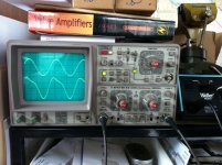
The scope screenshot shows the full 440Hz sine input signal (before pot) at the top, and the speaker output signal at about 3/4 of the volume at the bottom.
Where should I start looking for the cause for the distortion visible on the decaying side of the sine wave? It doesn't sound nice when the input signal is music, but is OK on lower volume.
Any thoughts from folks who have seen something similar and can provide some guidance would be appreciated.
Thanks!
sorry for the double-post from here http://www.diyaudio.com/forums/tubelab/195101-tubelab-se-checkout-shows-300v-bias-voltage-2.html#post2687568
Since the question is a generic, I hope to get a larger audience with potential ideas.
The scope screenshot shows the full 440Hz sine input signal (before pot) at the top, and the speaker output signal at about 3/4 of the volume at the bottom.
Where should I start looking for the cause for the distortion visible on the decaying side of the sine wave? It doesn't sound nice when the input signal is music, but is OK on lower volume.
Any thoughts from folks who have seen something similar and can provide some guidance would be appreciated.
Thanks!
Attachments
My first guess would be some kind of output tube loading issue -- with the transformer, or otherwise -- particularly since the test frequency is midband. What power level does the bottom display represent?
Dave
It starts at about three quarters of the full volume. Output tubes are Chinese 300B (Guigang), OPTs are UBT-3.
I have another set of 5K transformers that I can try, but they look a little skimpier than the UBT-3
I just did some more testing and the symptoms are similar across the frequency band, although more pronounced at low frequencies, which seems reasonable.Grid current limiting?
What I did notice - in support of your theory - is that one channel is worse than the other. The 'bad' side's grid resistor current rises with volume much more than the other side. I stopped at 130mA to not artificially limit the tube's life.
Could a bad MOSFET be the cause? I'll go back and check to make sure I put the correct 20K resistor on both sides. If OK, I guess I will replace the MOSFET and see what happens.
Thank you!!!
Triple checked all components for correct value, but the problem persists. Swapped output tubes, but the problem didn't follow. It's way more pronounced on the right channel than on the left, although visible there too.
Re-adjusted bias and it remains stable for the lower half of the volume spectrum, after which the right channel rises quickly. At full volume, right channel bias current is almost double of the left channel.
Haven't replaced the MOSFETs yet, because they are a Royal Pain Diaz to get out (heatsinked and bottom-mounted), but that's the last thing to try, I guess.
Music starts to sound pretty awful when played at higher volume.
I noticed that the sine wave distortion seems to affect the falling flank on the signal with lower frequencies (<400Hz), but moves over to the rising flank on higher frequencies (which is when the cats in the neighborhood started whining... ).
).
Anyway, if anybody has another idea of what may be going on, please let me know.
Cheers,
Stefan
Re-adjusted bias and it remains stable for the lower half of the volume spectrum, after which the right channel rises quickly. At full volume, right channel bias current is almost double of the left channel.
Haven't replaced the MOSFETs yet, because they are a Royal Pain Diaz to get out (heatsinked and bottom-mounted), but that's the last thing to try, I guess.
Music starts to sound pretty awful when played at higher volume.
I noticed that the sine wave distortion seems to affect the falling flank on the signal with lower frequencies (<400Hz), but moves over to the rising flank on higher frequencies (which is when the cats in the neighborhood started whining...
).Anyway, if anybody has another idea of what may be going on, please let me know.
Cheers,
Stefan
Diagnosis
Well, you've scoped the amplifier input signal and output signal to the load. You have a linearity problem... so, why haven't you scoped the grid of the output tube to see what it's drive signal looks like? If it's the same, then the output stage is just following input and you back up to the next stage of the circuit. If the grid drive matches the input signal then you've isolated the problem stage. I'd scope each stage input/output to see where it breaks down... why guess?
Regards, KM
Thanks for the suggestion, KM. Did I mention that my experience with using the scope in this 'environment' is limited?
I did try to see the output signal coming into the 300B grid, but as soon as I turn on the amp, the bias current rises above 1A and there is really bad static, which can't mean good things, so I pulled the plug. I may just be too you-know-what to use the scope properly, so I'll read up on proper scope settings and usage for this scenario.
Maybe I need to park this for a couple of days and come back with a fresh set of eyes and ideas, who knows.
Thanks again for responding!
StS
It starts at about three quarters of the full volume. Output tubes are Chinese 300B (Guigang), OPTs are UBT-3.
I have another set of 5K transformers that I can try, but they look a little skimpier than the UBT-3
the scope is set to 2 v/div. I think this works out to about 1 watt if the load is 8 ohms. If so then I'd swap in this other OPTs just to see what happens. If you use 440Hz as the test signal their size (or lack of it) will not matter.
Maybe the OPT is saturating? Is the bias current within the OPTs spec? Is it getting close?
Last edited:
the scope is set to 2 v/div. I think this works out to about 1 watt if the load is 8 ohms. If so then I'd swap in this other OPTs just to see what happens. If you use 440Hz as the test signal their size (or lack of it) will not matter.
Maybe the OPT is saturating? Is the bias current within the OPTs spec? Is it getting close?
Thanks Chris, I have swapped out the OPTs yesterday, symptoms persist. This is a proven design (Tubelab SE) and I am currently just running at the initial Bias setting of about 50mA.
I quadruple-checked all relevant components for proper value, so I think I can rule that out as an issue. Maybe I don't really have an issue!? I could almost convince myself of that if
a) the amp would sound as I had expected it to sound and
b) the bias current would rise roughly the same amount in both channels with volume.
But I am missing the clarity I've heard in my Simple SE and the right channel bias current ends up being almost double at full volume, with very audible distortion. I don't think that's right. Then again, I am pretty new to this.
I think I am going to reconfigure the board to use 45s and see what happens. A desperate move indeed, but one that I had planned to try anyway.
Thanks for your response!
measurements
Well, I don't believe that "easter egging", i.e., swapping parts will solve your problem. Look at the spec sheet for the UBT-3 OPT. If you use a 300B, you should have a plate voltage around 325V (plate to cathode) and a cathode current around 75ma. With a proper driver circuit, you should see a pretty clean 7-watts output. Take some voltage measurements on the tube socket itself and see where you fit into the curves.
Western Electric
If you're good against some common operating points, then you need to start scoping each stage of the amplifier to see where things go wrong. Start at the grid of the 300B and see what the waveform looks like as you increase the signal drive level.
Regards, KM
- Status
- This old topic is closed. If you want to reopen this topic, contact a moderator using the "Report Post" button.
- Home
- Amplifiers
- Tubes / Valves
- Output signal distortion