hi guys
i just build a 112a preamp and would love any comment, idea, critics. please...
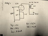
i attached the schematic.
however my concern that it drift from the datasheet
my concern is: with my operating Va=152va. According to 112a datasheet, Vg should be around -10v with auto bias. but the actual circuit i got Vg= -15v.
i tried 3 different brand of 112a tubes and they are all around Vg= -14.4 to 15.3v
anything that i did wrong? it does sing well though. or its should be ok and i could leave it like that?
thanks in adv
Erwin
i just build a 112a preamp and would love any comment, idea, critics. please...
i attached the schematic.
however my concern that it drift from the datasheet
my concern is: with my operating Va=152va. According to 112a datasheet, Vg should be around -10v with auto bias. but the actual circuit i got Vg= -15v.
i tried 3 different brand of 112a tubes and they are all around Vg= -14.4 to 15.3v
anything that i did wrong? it does sing well though. or its should be ok and i could leave it like that?
thanks in adv
Erwin
Attachments
hi Thomas
thanks for the reply. its below the rated indeed. one is 4.5v and the other one is 4.8v. havent fix this yet. should be able to get both to 4.8v.
but with both filament of different voltage. the grid voltage is roughly 15v as well.
do you think i should opt for fix bias?
erwin
thanks for the reply. its below the rated indeed. one is 4.5v and the other one is 4.8v. havent fix this yet. should be able to get both to 4.8v.
but with both filament of different voltage. the grid voltage is roughly 15v as well.
do you think i should opt for fix bias?
erwin
Hi Erwin,
how did you connect the filament supply? I assume it is DC.
If the - side of the filament supply is connected to the filament terminal with the cathode resistor, the bias voltage is increased by 2.5V. If it is connected the other way, the bias is decreased by 2.5V. I assume that is the case, that would explain the higher current, because your bias in that case would actually be 12.5V
Thomas
hi thomas
yep thanks you. you got the points there. i should check on this. yeah the drift is 5v which is the filament voltage. maybe they are some how related")
i am using rod's regulator and connect them as instructed. which is positive side of the filament regulator to the cathode resistor pins. and the regulators are floating.
yep thanks you. you got the points there. i should check on this. yeah the drift is 5v which is the filament voltage. maybe they are some how related
i am using rod's regulator and connect them as instructed. which is positive side of the filament regulator to the cathode resistor pins. and the regulators are floating.
Hi!
The datasheet values are always given with relation to the mid point of the filament. that means the bias voltage is increased or decreased by half the filament voltage, depending on how it is connected.
The bit of extra current will not hurt the 112A. I would leave it as is
Thomas
The datasheet values are always given with relation to the mid point of the filament. that means the bias voltage is increased or decreased by half the filament voltage, depending on how it is connected.
The bit of extra current will not hurt the 112A. I would leave it as is
Thomas
Hi Erwin,
I don't think there is any problem, either!
Normally, using the filament + terminal for the cathode resistor is best - but you can try for yourself and connect the cathode resistor to "filament -". Recheck the cathode voltage - and expect it to be LOWER (ie, lower anode current).
You can run it either way around - let your ears be the judge. BUT, be sure to check that they are connected the same on both sides - or the sound will be very odd.
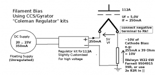
Erwin, you asked me also how to use the 112A in the filament bias configuration - like Andy's #26 circuit.
The big difference if you use filament bias - you MUST connect the negative terminal to the cathode resistor (or the bias will not work).
Hopefully, the drawing shows all you need to make this circuit.
As Thomas describes, the effective bias voltage is the mid-point between the filament terminals, so in this case (with filament -ve connected to cathode), we only need to generate about 10V in the cathode circuit. As shown, a 39 ohm wirewound, that can comfortably handle the 2.5W dissipation, is recommended. Unless you have a favourite exotic type, I recommend the Welwyn W22, W23, W24 series of vitreous enamelled wirewounds.
The 250mA Filament regulator will work like this, but capacitor C1 needs a higher voltage rating (47uF, 35V Panasonic AM audio series), and R8 changed to be 1,8K 0,5W.
Finally, note that filament bias can slightly reduce the effective gm of the DHT. Bypassing a 39R resistor would require a large and unpleasant electrolytic, so you will not want to try that, I suspect. For instance, if you operate the 112A such as to achieve 1,8mA/V - a 39R in the cathode reduces it to 1,7mA/V, so you get a very small drop in gain.
Note that with, high gm, or high Rk, this gain loss effect is important to be aware of.
Attachments
Hi - yes, filament bias will work nicely.
The dissipation of the 39 ohm resistor is 2.5W. I would use a higher wattage than 6W, because experience tells me this gets very hot. If it's inside the chassis then the whole of the inside gets hot including the top plate. I'd go for 12W or even more.
I found that using choke input in front of Rod's regulator made an audible improvement. Plenty of chokes are available from Hammond to do this. You can use a small input cap like 220uF, and main cap should be 20,000 to 40,000uF. More is better. The supply needs to be very smooth with filament bias.
andy
hi guys
thanks a lots for the inputs. as usual, all is really appreciated.
its clear now. for the moment i will just leave it as it is. sounds amazing as it better matched my Line output transformer (58H) compare to 26 which has higher Rp
i am using 0.25mH-15mF-0.47R-22mF for the raw.
Rob, i am running the 112a on 4.5Vdc as the transformer cant keep up and the trimpot does nothing to change the voltage at the heater pins. would you think its ok ? or i need to get another transformer?
Erwin
thanks a lots for the inputs. as usual, all is really appreciated.
its clear now. for the moment i will just leave it as it is. sounds amazing
as it better matched my Line output transformer (58H) compare to 26 which has higher Rpi am using 0.25mH-15mF-0.47R-22mF for the raw.
Rob, i am running the 112a on 4.5Vdc as the transformer cant keep up
and the trimpot does nothing to change the voltage at the heater pins. would you think its ok ? or i need to get another transformer?Erwin
Hi!
That's right. But as Rod says the impact is really negligible. The reason why I came up with filament bias was to eliminate the cathode bypass cap. So putting in a cap again seem pointless.
When I use filament bias i still use ultrapath as well. cathode resiistor goes from the negative filament terminak to ground. I connect the ultrapath cap to the positive filament end.
Best regards ... Thomas
Finally, note that filament bias can slightly reduce the effective gm of the DHT. Bypassing a 39R resistor would require a large and unpleasant electrolytic, so you will not want to try that, I suspect. For instance, if you operate the 112A such as to achieve 1,8mA/V - a 39R in the cathode reduces it to 1,7mA/V, so you get a very small drop in gain.
That's right. But as Rod says the impact is really negligible. The reason why I came up with filament bias was to eliminate the cathode bypass cap. So putting in a cap again seem pointless.
When I use filament bias i still use ultrapath as well. cathode resiistor goes from the negative filament terminak to ground. I connect the ultrapath cap to the positive filament end.
Best regards ... Thomas
Hi!
This is very true !!!!
Thomas
Poor quality filament transformers, or too small - will destroy the amp's potential for best sound performance.
This is very true !!!!
Thomas
Hi!
This is not a true choke input. The L needs to be of a minimum size for the supply to act as choke input. That would require an inductance about 50 times higher. But on the other side that would cause an even lower output voltage, so doesn't help with that problem.
Your new filament transformers should fix that
Thomas
i am using 0.25mH-15mF-0.47R-22mF for the raw.
This is not a true choke input. The L needs to be of a minimum size for the supply to act as choke input. That would require an inductance about 50 times higher. But on the other side that would cause an even lower output voltage, so doesn't help with that problem.
Your new filament transformers should fix that
Thomas
A bias of 4.5v at 5mA with 90v anode would require a cathode resistor of 18 ohms.
Add the 5v of the filament and the supply needs to provide 9.5v. Add 5v and Rod's board needs an input of approx 14.5v. Add 1.5v for the choke and you get 16v. An 18v primary should just do this, I presume. Bit close. Anyway, you can see the kind of calculations you have to make.
Add the 5v of the filament and the supply needs to provide 9.5v. Add 5v and Rod's board needs an input of approx 14.5v. Add 1.5v for the choke and you get 16v. An 18v primary should just do this, I presume. Bit close. Anyway, you can see the kind of calculations you have to make.
hi guys
i am using 0.25mH-15mF-0.47R-22mF for the raw.
sorry guys. its typo
25mH-15mF-0.47R-22mF for the raw.
nice. how bout 25mH 2a?Hi!
This is not a true choke input. The L needs to be of a minimum size for the supply to act as choke input. That would require an inductance about 50 times higher. But on the other side that would cause an even lower output voltage, so doesn't help with that problem.
Your new filament transformers should fix that
Thomas
whats the requirement or tips on choosing input choke either for B+ or Filament?
Erwin, probably the trafo is too low voltage, or too small.
9V or 10V, (rated 20VA or more) is recommended. Poor quality filament transformers, or too small - will destroy the amp's potential for best sound performance.
yeah i suppose its not enough voltage at the 1st stage. quality is ok and big enough as its suppose for 26
Thanks Andy for the hammond suggestion, i would have a look at them. the calculation really helps me to get a hang of it
thats really informing. very nice. thanks a lot guys. i am learning a lot. guess i am ready for the next project
full set power amp from the help of you guys in the other thread. i will update that thread but will take months please bare with methanks in advance for all the helps
Erwin
- Status
- This old topic is closed. If you want to reopen this topic, contact a moderator using the "Report Post" button.
- Home
- Amplifiers
- Tubes / Valves
- 112a preamp need comment please