...
So I devised a relay that is placed in series with the filament of the rectifier, is powered by the filament voltage, uses 5v relay and 10v caps for small size, and delays the power up of the rectifier by 20s which gives ample time for the output tubes to heat up and present a load ...
I saw this solution mentioned somewhere else, and it seems to tick all the boxes. I like the idea that a hot restart will still have a delay, unlike the use of thermistors.
This is a very cool idea, and inherently "fail safe" if the relay or its timer fails to hold someday, a worthy idea for some schematics. Id be inclined to energize the relay from the filament supply of the tubes you are trying to protect and not the 5v one, even more fail safe. Delay and slow start using a rectifier thats been sitting there all along!
Getting a DC "whack" may prove to be fatal. Basically getting a "whack" is a failure to take safety precaustions seriously and that should be a wakeup call: it should never happen.
I wonder how many of the esteemed posters, guru's and current crop of authors on valve technology have actually studied valve technology at varsity.
Many years ago I came to this forum looking for answers, unfrotunately over the years I have come to realise that there are so many misinterpretations, misconceptions and ego's that it is too often dangerous to take blindly advice from posters on the internet. It appears to have gotten worse as times moves on.
Unfortunately it appears to be a sign of the times that many posters want instant answers and results without having to apply themselves. In the case of valve technology they have no business working with the high DC voltages involved - they are like the children that have a gun to play with.
If I want to know something I go back to the books of the old masters, who devised the components and worked out the best way to utilise them. If failing to find an answer then, ond only then and not before, I go searching but always examine the solution and never blindly follow.
Stay safe and don't electrocute yourself.
I am returning to your circuit from post #18. Perhaps, you should show the whole PSU using your regulator. As I understand it, it can't be used with with CT transformers and 0 GND is more or less floating through Q3. Am I right?
For such an old thread (10 years!) still alive, I appreciated everyone's desire to solve this with technology. But it is a a solution to a problem that doesn't exist. The first post on this thread was the correct answer IMO... "I prefer to have separate power and plate supply switches. This is simplest. Then you can also put the amplifier to stand-by mode." I started in the 80s, all my amps are built this way... and it never messes up. It costs and takes the addition of a nice switch. Not years of debate and research...
I'd still be interested to know what's going on with C104 & R113 on the cascoded MOSFETs. Doesn't look right to me, Q2 is going to end up dissipating nearly all the heat?Complete Article published in AudioXpress Magazine 2004.
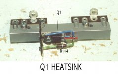
OK Merlin, the cct does not defy the Laws of Gravity or deny Kirschhoffs Laws of electricity.. At switch on C104 forces equal voltages across R111 & R112 so that Q1 & Q2 share the full voltage drop from the rectifier stack to the load.
As you have pointed out, Q2 will eventually drop nearly all the excess voltage & dissipate most of the heat. That allowed a large Wakefield heatsink on Q2 & a much smaller heatsink on Q1. That formed by a simple piece of extruded Aluminum.
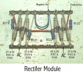
Some folks may wonder what so many rectifiers & resistors look like in one place. For a 'One Of' build it hardly makes sense to cobble together a PCB. That coupled with the fact I'd never done a PCB, a very simple solution in this case uses a pair of terminal strips. Temporarily mounted on a wood scrap, all the parts are put in place & solder applied. A simple & slick solution. I've often used that technique with very good results.")
As you have pointed out, Q2 will eventually drop nearly all the excess voltage & dissipate most of the heat. That allowed a large Wakefield heatsink on Q2 & a much smaller heatsink on Q1. That formed by a simple piece of extruded Aluminum.
Some folks may wonder what so many rectifiers & resistors look like in one place. For a 'One Of' build it hardly makes sense to cobble together a PCB. That coupled with the fact I'd never done a PCB, a very simple solution in this case uses a pair of terminal strips. Temporarily mounted on a wood scrap, all the parts are put in place & solder applied. A simple & slick solution. I've often used that technique with very good results.
Attachments
- Home
- Amplifiers
- Tubes / Valves
- Simple B+ delay circuit for tube power amp?