Member
Joined 2009
Paid Member
I thought this was a question that would already have been asked but I didn't turn up much with a search. Seems to me that tubes = class A.
Coming from the SS side of life the Class AB amp is common. And has been researched to death. One is left feeling that for the most part, it's a topology that needs plenty of gnf. But it's a technology that has been refined and works well.
So what about tubes, they have different characteristics from transistors - how is the cross-over from class A to class B - is there an optimal bias ?
I get the perception Class AB tube amps are rare - why ?
No, tubes don't mean class A. For transistor amps class A matter much more than for tube amps that work nice in class AB. Actually, class AB nonsense in transistor amps was the result of attempts to mimic class AB tube amps. First transistor amps even used output and interstage transformers. Today Teransformerless word is omitted and forgotten, but it was used when transformers for the first time were eliminated from transistor amps.
Yes, there are optimal biases, that depend on selection of limiting factors, such as power dissipation, real word transformers, geometries of tubes.
Plate curves are your friends dear Bigun!")
Yes, there are optimal biases, that depend on selection of limiting factors, such as power dissipation, real word transformers, geometries of tubes.
Plate curves are your friends dear Bigun!
Last edited:
In fact, most of the amplifiers produced in the heyday of the vacuum tube production used class AB1 output stages -- Virtually all Dynaco, Fisher, Heath, Eico, Scott, Pilot, etc. were all class AB1 amplifiers to name but just a few. Even most of the Mac stuff was class AB. More to the point, it is true class A amplifiers that are rather rare with vacuum tube amplifiers. The original Williamson design is an exception to this, as it was quite common, and was a true class A amplifier with a triode output stage.
There is always an optimum bias point, but depending on how the tubes are operated, this can be very sharply defined (i.e pentode operation), or more broadly defined (as is typical with UL operation). How well the crossover point behaves is primarily a product of the quality of output transformer used.
Dave
IMO, most transistor amps are "class AB" and most valve amps are "class AB", however the term "class AB" has a totally different meaning in those two worlds. An interesting metric is the ratio of quiescent current to peak current for the output devices.
For example in a solid-state 50W/8ohm amp, the output devices have to deliver a peak current of about 3.5A, yet the idling current is often only about 100mA - around 3% of peak. If the idling current was increased to 350mA, that would be considered as "very high bias", yet it is still only 10% of peak current.
I think if the idling current in the output valves of a tube amp was only 10% if the peak current, the amp would be considered hopelessly underbiased.
Maybe some tube-heads can give an idea of what's typical in a valve amp?
IMO, most transistor amps are "class AB"
Nup: the most famous opamp that sold xx millions in hi end audio and studio consoles uses class B was the 5534....thd 0.002% and a noise floor well below -90dBu ?
Member
Joined 2009
Paid Member
very interesting. I feel a need to start inhaling more information on this topic. My diy audio education seems to have a huge gap in it ! I had thought tube class ab was not a good idea because it was so much better to do it in SS where complementary n an p type devices are available.
Plate curves my friend - will have to look - It matters now how do tubes turn on-and-off compared with bipolar transistors - do they make better transition than typical SS ?
Perhaps the question I really need to ask is: What do you think I should expect in terms of 'sound' from tube class ab amplifier - is it possible to achieve good results without gnf without a complex design / tricks - do I look to these old designs Dave listed out or is there a modern 'standard design' approach (like the double EF for SS class AB) ?
p.s. yes, no opamps here !
Perhaps the question I really need to ask is: What do you think I should expect in terms of 'sound' from tube class ab amplifier - is it possible to achieve good results without gnf without a complex design / tricks - do I look to these old designs Dave listed out or is there a modern 'standard design' approach (like the double EF for SS class AB) ?
Even AB2 is possible (grid-1 current) with the right drive and suitable output tubes. Don't know if it can be called complex design or tricks but it does work. Judge yourself from schematics.
My 2C34 AB2 PP-amp's playing behind me right now.
Sounds wonderful.
Thread here: http://www.diyaudio.com/forums/tubes-valves/189653-cf-ccs-can-made-simpler.html
Newly re-drawn and corrected schematics attached.
rgds,
/tri-comp
Attachments
Last edited:
The "Big 3" of vintage tube amps, Marantz 8B, H/K Cit. 2, and McIntosh 375, are all Class "AB1". The class of operation for both tubes and SS is defined by the duty cycle. Class "A" entails a 100% duty cycle, Class "B" entails an exactly 50% duty cycle. Class "AB", naturally, falls between "A" and "B". With Class "AB", you really need to state whether the unit is operating near Class "A", near Class "B", or truly in betweeen.
IIRC, Krell offered Class "A" SS amps that ran quite hot, as is too be expected.
IIRC, Krell offered Class "A" SS amps that ran quite hot, as is too be expected.
is it possible to achieve good results without gnf without a complex design / tricks - do I look to these old designs Dave listed out or is there a modern 'standard design' approach (like the double EF for SS class AB) ?
There are two new designs that come to mind that fit the requirements. Both can be built to power levels from a few WPC to hundreds of WPC. Both are very long threads revealing multiple build options.
A poster asked how to build an amplifier using 6L6GC's in AB2. He was looking for about 25WPC. Together we designed an amplifer that can run in class A , AB1 or AB2 in pentode, UL, or Triode mode. I ran several types of output tubes at power levels from 15 WPC to 100 WPC, but never made a finished amp out of it. None of my versions needed or used GNFB or any local feedback. Chris however did build a nice amp that looks and sounds good. I don't remember if he used GNFB.
http://www.diyaudio.com/forums/tubes-valves/133034-6l6gc-ab2-amp.html?highlight=6L6GC+AB2
Pete Millett designed a mild mannered 18 WPC P-P AB1 amp using sweep tubes. I bought one of his boards and remarked that I would be disapointed If I didn't get at least 50WPC. I set my sights too low. I have seen the board make 250 WPC for a weekend of very loud music, but settled on a "conservative" and very stable 125 WPC build. Several people have built the 125 WPC version. I am not the only one who likes the sound. The board has the option of running GNFB. I tried it for about 2 minutes and unhooked it. It is much more dynamic without GNFB, but some local feedback around the output tubes is used.
http://www.diyaudio.com/forums/tube...p-p-power-amp-design.html?highlight=6L6GC+AB2
You can't get 200+ WPC from a TRUE Class A amp using tubes, silicon, GaN, SiC, or nuclear fusion unless you have the cooling system from an old Cray super computer lying around. Sales and marketing people have been known to stretch the definition of "Class A" just a bit.
maybe not in S Fl, but up here I dump >500 W electrical power into my apt all winter long
It is a rare year that I even turn the heat on for a day. There was a week or so last winter where the temps stayed in the 30's for several days and all the strawberries and oranges froze, but I was up north playing in the snow so I missed it.
A 200 WPC class A amp would dissipate between 500 amd 1000 watt s of heat. Here in the land of year round air conditioning. I would pay for the electricity to make that heat, and pay much more to remove it from the house. I have a 40 WPC class A2 tube amp, but it hasn't been turned on in at least 2 years. It's rather efficient for a class A tube amp and it still makes about 500 watts of heat.
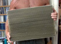
Now when and if I ever decide to make that big class A Zen amp, I got my heat sink. Already populated with 24 big mosfets. Carrying this thing the 1/2 mile back to the car at the Dayton Hamfest wasn't much fun.
Attachments
Question if I may, how good were the early transformer coupled solid state amps?
I ran across a Magnavox stereo console with such an amp and am tempted to make an offer for it but really don't need it.
I'm curious about how well they worked.
Like this one, Astro-Sonic:
Magnavox Astro-Sonic Stereo FM/AM Radio - Phonograph | eBay
The bass speakers in this stereo look like they are 16"!
Last edited:
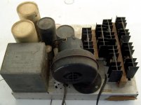
Aha, so that is what the transformers were for.
Those speakers look huge!
They also have another console with horn mid range speakers and a third that has got to be 8' long with totally sealed speakers on the ends. I'd love to get them cheap just to tear them apart but probably am best to forget it.
Those speakers look huge!
They also have another console with horn mid range speakers and a third that has got to be 8' long with totally sealed speakers on the ends. I'd love to get them cheap just to tear them apart but probably am best to forget it.
like you i go around the house shirttless most of the day, i sweat a lot and if i don't remove my shirt, it goes dripping in no time,
I can sweat up a shirt just walking across the parking lot at work this time of year. The older I get the worse it gets. My father was the same way. Inside the house with AC on it's never really cool. It costs too much to run the AC below about 78 degrees. It looks like you are a bit closer to the equator than we are.
awsome looking heatsink btw......
It's got a 5 KW RF amplifier attached to the other side. It's from a big MRI machine so it isn't for continuous duty. $75 at the Dayton hamfest.
Question if I may, how good were the early transformer coupled solid state amps?.......They had transformerless outputs, but transformer phase splitters. .......Aha, so that is what the transformers were for.
Almost all of the amps produced in the late 60's and early 70's used the same circuit that had a pair of 2N2147 germanium power transistors per channel in a totem pole design. I had a Heathkit AR-13 receiver at the time. Same circuit. I thought it sounded really good but I was 17.
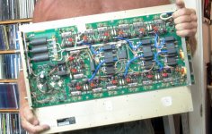
I used that sane design to make some really BIG solid state amplifiers in high school. One had 24 X 2N3773's running off of rectified wall outlet (I was 17 and stupid) We saw it make 1200 watts into a 2 ohm load. It was stronger than any speaker available in 1970. I last saw it in the mid 80's and it was still alive. I just replaced the Fosters sized caps and sent it on its way. The picture shows a 300 watt version I made in 1968 using 6 X "special" 2N3055's. The transistors were military surplus and they would eat over 100 volts without blowing up. I still have some somewhere from 1968.
Attachments
- Status
- This old topic is closed. If you want to reopen this topic, contact a moderator using the "Report Post" button.
- Home
- Amplifiers
- Tubes / Valves
- Class AB PP - is it any good ?