
Wood Chassis, Some assembly required
Some assembly required; take part A,(wrong size), insert in part B,(not included), use instructions (in Latin) if all else fails. Help line is "Dial a Prayer"...
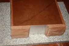
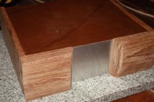
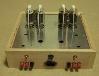
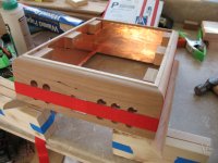
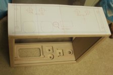
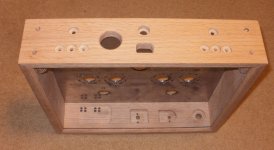
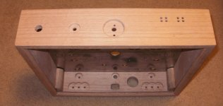
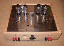
I do a 3 sided box with removable back. All sides slotted for the top plate to slide into place. Also bottom plate can slide into place. No screws from top or sides. Corners are 45 deg, back held in place 2 screws on each side.
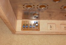
I use a forsener bit to drill the recesses in the front or through hole for the amp gage and nixie tube. Also use it to recess the back side to get the front to the correct thickness for the power switch, volume pot, phonojack input for MP3 and bias switch.
The aluminum top plate is more of a challenge to slot the vent holes on a mill with centering jig at the tube centers.
Lots of sanding , a little stain and 7 coats of tung oil....
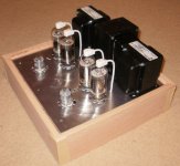
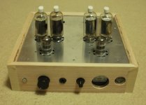
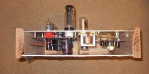
The top plate is assembled as far as possible and then slid into place for the final wiring to the front and back. Add tubes, fuse, power, input, speakers and cold beer, power up and adjust bias, crank it up...... AHhhhhhhh
Some assembly required; take part A,(wrong size), insert in part B,(not included), use instructions (in Latin) if all else fails. Help line is "Dial a Prayer"...
I do a 3 sided box with removable back. All sides slotted for the top plate to slide into place. Also bottom plate can slide into place. No screws from top or sides. Corners are 45 deg, back held in place 2 screws on each side.
I use a forsener bit to drill the recesses in the front or through hole for the amp gage and nixie tube. Also use it to recess the back side to get the front to the correct thickness for the power switch, volume pot, phonojack input for MP3 and bias switch.
The aluminum top plate is more of a challenge to slot the vent holes on a mill with centering jig at the tube centers.
Lots of sanding , a little stain and 7 coats of tung oil....
The top plate is assembled as far as possible and then slid into place for the final wiring to the front and back. Add tubes, fuse, power, input, speakers and cold beer, power up and adjust bias, crank it up...... AHhhhhhhh
Attachments
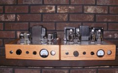
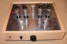
Nothin' like Nixies here just some Padauk and shellac for the finished amp; the unfinished pre-amp chassis' native walnut will get Natural Watco, then shellac. The amps top plate is powder coated 1/8" aluminum, the pre-amp and all subsequent plates will get anodized. Powder coat smudges and marks just from dusting. Who knew?
Attachments
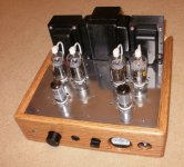
Compactron Hybrid Headphone Amp.
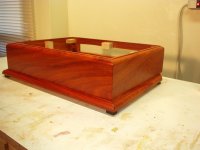
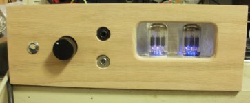
A dedicated headphone amp, Hybrid circuit tube 1st and 2nd stage with a Mosfet class A follower for low impedance drive capability. Just got the box glued up, prior to the sanding marathon, staining and 8 coats of tung oil. This Amp is designed to be the base unit under either of the power amps above, same foot print. It uses the same compactron triple triode as the first and second stage in the power amp. There are more than 5 compactrons that can be swapped out, Ive tried the 6u10, 6ac10, 6ak10, 6av11 and 6d10.
After I through an extra winding on the toroid that I had, I found an Antek that was a direct drop in. just slightly larger in size
I tried to cut a piece of glass for the window, with little success. Decided to use a piece of lexan instead.
Attachments
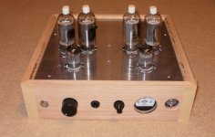
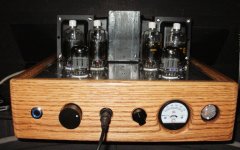
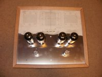
Chassis construction KEG-EAR Amp
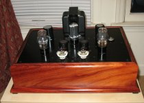
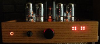
A 6L6-KT88 based amp with the same basic box design. This one has LED bias monitor instead of a nixie-amp meter combo.
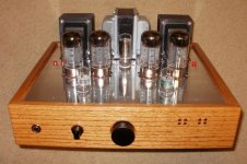
The top plate is machined by a combination of drill bits, stepped drill bits for the transformer wire pass holes, Greenlee punch for the tube holes, and a milling machine for the slotted tube holes. I spend a couple hrs polishing the top plate after deburring and sanding the tube holes.
The front and back are machined with forstner bits and a dremmel tool with a router bit. The components are verified for fit and then the sanding marathon and assembly start. The front and sides are joined and the top and bottom plates just slide in the saw kerfs. The back secures the assembly.
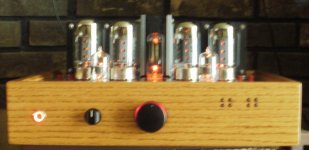
I pre-wire the top plate assembly and also pre-wire the wood chassis. Slide the top plane in and complete the wiring. After initial fire-up, bias voltage confirmation, slide the bottom plate in place to finish the Amp.
The bias monitor is switched, you can watch the tubes bias up and twinkle to the music, or just turn them off...
A 6L6-KT88 based amp with the same basic box design. This one has LED bias monitor instead of a nixie-amp meter combo.
The top plate is machined by a combination of drill bits, stepped drill bits for the transformer wire pass holes, Greenlee punch for the tube holes, and a milling machine for the slotted tube holes. I spend a couple hrs polishing the top plate after deburring and sanding the tube holes.
The front and back are machined with forstner bits and a dremmel tool with a router bit. The components are verified for fit and then the sanding marathon and assembly start. The front and sides are joined and the top and bottom plates just slide in the saw kerfs. The back secures the assembly.
I pre-wire the top plate assembly and also pre-wire the wood chassis. Slide the top plane in and complete the wiring. After initial fire-up, bias voltage confirmation, slide the bottom plate in place to finish the Amp.
The bias monitor is switched, you can watch the tubes bias up and twinkle to the music, or just turn them off...
Attachments
-
 9.1 fired_up1c.jpg67.6 KB · Views: 47
 -
 8.0 Assembled_b.jpg156.1 KB · Views: 52
 -
 7.15 bias monitor.jpg110.3 KB · Views: 46
 -
 7.1 chassis back.jpg92.6 KB · Views: 41
 -
 7.0 chassis front.jpg73.1 KB · Views: 50
 -
 6.3 chassis side_c.jpg111.2 KB · Views: 51
 -
 6.2 chassis back.jpg761.5 KB · Views: 39
 -
 6.1 chassis front.jpg118.7 KB · Views: 44
 -
 4.1 chassis.jpg737.3 KB · Views: 54
 -
 9.2 fired_up7.jpg377.5 KB · Views: 48
Last edited:
- Status
- This old topic is closed. If you want to reopen this topic, contact a moderator using the "Report Post" button.
- Home
- Amplifiers
- Tubes / Valves
- BOX in the making