I have noticed that section #1 of a 6CM7 dissimilar dual triode looks exactly like a 6FQ7 / 6CG7 / 6SN7 element, even down to the details of the grid design. Testing it in a curve tracer against the others shows no difference. Although section #1 is rated at 1.45 watts it is the same size as section #2 which is rated at 6 watts, and the same size as the 6FQ7 / ../.. Looking at the GE data sheets it has similar curves to the others but not exactly the same, mainly due to the reduced range it is characterized over. If it looks like a sheep, and it smells like a sheep, it must .... well you know! Any comments on this?
By the way, there are some 6CM7 tubes marked made in Japan which have smaller plate size, about 2/3 size. Measure a little different.
Another tube of interest is the 6CS7. The Sylvania versions have dissimilar size sections that correspond to the watt ratings, but the RCA versions look exactly like the 6CM7 with both elements the same size, and don't look anything like the Sylvania design. These measure the same as the 6CM7 too, just slightly different pinout. Both 6CM7 and 6CS7 have similar specs. RCA maybe just put existing tooling to use?
Don
Hello smoking-amp.
Section I of the 6CM7 looks very similar to a 6SN7, and the killer is that Cag is the same, but the 6CS7 has different Cag (according to RC-30).
What sort of a curve tracer were you using? When you investigated increasing a pentode's suppressor grid beyond 0V, did it have any other effects on the curves other than moving the knee closer to 0V and flattening them? I ask because both these effects make a practical valve closer to the ideal, so you have to ask why the suppressor grid was normally tied to the cathode. (Television sync separators did elevate g3, but they operated in a non-linear fashion.)
Hello EC8010 and Sch3mat1c (Tim just saw your reply after I posted!)
I have been using a homebrew setup for a curve tracer: TEK7603 in x-y mode for display, a full wave rectified (unfiltered) HV xfmr. supply to sweep plate voltage, a plate resistor to HV with a Tek5200 HV Diff. probe to measure plate current, another Tek5200 HV Diff. probe to measure plate voltage (an ordinary probe would do here), and either a CMOS counter with D/A for grid step voltage or a very slow sweep generator ramp voltage for grid. I've been comparing traces between tubes by tracing off screen onto paper. I really should set up with two tube sockets and some reed relays on grids to alternate, would be more accurate and faster for comparisons.
On the pentode suppressor grid tests on dual control tubes (I tested 6LE8, 9KC6 and 6BV11 tubes) the knee moves closer to 0V and sharpens, the rest flattens. Nothing else obvious. Tried this on a normal pentode 6HB6 (comes in two flavors as pentode and beam tetrode, has G3 pin) and a couple beam tetrodes with separate G3 pin 12HL7/12GN7 and don't see much effect with either. Leaving the G3 unconnected had some interesting results on these, but cannot measure voltage on the pin without affecting and is not so repeatable. Looks like only a close mesh G3 has a big effect. I am aware of one power tube, the 6JQ6 which had an internal diode for biasing the G3 at +5V with respect to the cathode. Have seen some info in the RCA book "Electron Tube Design" which discusses using positive voltage on G3 of horizontal output tubes to suppress "snivets" in TV displays, think this has to do with oscillations around the knee.
Snivets!
Your curve tracer setup sounds interesting. It is high time I knocked up something similar. Perhaps this could be the justification for a suitably sensitive current probe.
Your results suggest that it ought to be possible to extract more power out of a pentode output valve by suitable tweaking of suppressor grid voltage. I will now need to find out about snivets...
snivets and curve tracer
snivets! They sound like some kind of bugs don't they!
Probably by increasing the G3 voltage it prevents some kind of unstable charge buildup between G2 and G3 due to the G2 deflected electrons having marginal directed velocity to get by the 0V G3 when plate voltage is low. Although I don't see much obvious effect on the curve tracer for normal pentodes, maybe one gets some noise in an amplifier if one operates near the knee, so would be useful to up the G3 voltage a little. I think maybe I saw something written about the plate curve does not retrace the same exact path on increasing current versus decreasing current transitions thru the knee. Could be a problem just with the high current horizontal tubes, don't know.
The way I measure current for my curve tracer setup is by using a differential voltage probe (TEK P5200 HV Diff. probe, it has two short flexible leads with clips on them, good to 20 MHz) across the plate resistor. I suppose a current probe would work too, although the DC capable current probes are pretty expensive, even used. The differential HV probe has been probably the best investment I have made, it completely alters ones testing outlook when you can just clip onto any two points in a circuit. I think B&K instruments or one of the like has a cheaper version than the TEK.
Re: snivets and curve tracer
I should say so, and that's why I don't currently have one. I imagine you have to use a fairly sizeable current sensing resistor to drive your differential probe properly, which won't matter with a pentode, but would be more of a problem with a triode.
I've come to the conclusion that oscilloscopes are like cameras. The body isn't too expensive, but the manufacturer makes their profit on those essential "accessories" like lenses, or in this case, probes.
For the moment I can't imagine why elevating the suppressor grid by even 20V should cause a retrace problem, and if it doesn't show up on your curves, perhaps it doesn't exist. I'll have to give it some thought...
Snivets do indeed sound like a bug, and if they are oscillations, they will cause patterning to crawl over the screen.
smoking-amp said:...although the DC capable current probes are pretty expensive, even used.
I should say so, and that's why I don't currently have one. I imagine you have to use a fairly sizeable current sensing resistor to drive your differential probe properly, which won't matter with a pentode, but would be more of a problem with a triode.
I've come to the conclusion that oscilloscopes are like cameras. The body isn't too expensive, but the manufacturer makes their profit on those essential "accessories" like lenses, or in this case, probes.
For the moment I can't imagine why elevating the suppressor grid by even 20V should cause a retrace problem, and if it doesn't show up on your curves, perhaps it doesn't exist. I'll have to give it some thought...
Snivets do indeed sound like a bug, and if they are oscillations, they will cause patterning to crawl over the screen.
more on crawling bugs
The plate resistor in the curve tracer setup is necessary to limit max plate dissipation. The professional curve tracers have a big knob to select plate resistor or max current. So one automatically gets a generous current sensing resistor in this scheme. But true, in more general cases the sense resistor can be a problem or cause a noisy display if one has to crank up the scope gain too much.
Elevating the suppressor G3 is supposed to cure the snivets or retrace problem, not cause it. I was just speculating that the snivits problem might be related to the retrace problem.
Don
Poorly snivets
Agreed, professional curve tracers incorporate a selectable load resistor, but they apply feedback after that resistor to make the output resistance of the voltage source zero, otherwise it would distort the shape of the curves. The load resistor enables the protection circuitry to shut the tracer down once a particular loadline has been met, or a specified power dissipation is reached. Doesn't stop you destroying devices though. By definition, curve tracers are made to be able to test power devices and fragile ones, and they can't know that the operator has been daft enought to test something fragile on the big bolshy setting.
We really need to know for certain what these snivets are, even if elevating g3 cures them. I can't bear the thought of a poorly snivet.
a snivet here and a snivet there
Holy sniveling snivets Batman!
What'll they think of next?
- Robin - from"The Dynamic Duo"
looked thru all my tube books and the only one that mentions "snivet" is the RCA "Electron Tube Design" book.
Pages 741 and 742 "Circuit Troubles Caused by Unusual Tube Effects" by W. E. Babcock 1962
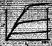
"A very familiar kind of interference from the horizontal- deflection circuit is the "snivet" type, shown in Fig. 11. One possible cause of snivet interference is illustrated in Fig. 12, which shows the plate-current, plate-votage characteristic of a deflection tube at zero bias voltage. When the plate current rises from zero to very high values it follows a smooth curve. However, when it decreases from very high values toward zero, there is a discontinuity in the curve. This sudden change in plate current produces harmonics which can be picked up by the rf amplifier and produce interference."
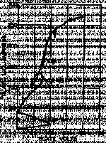
"Another theory holds that snivets interference is caused by a form of Barkhausen oscillation. This theory is logical because the plate voltage swings appreciably below the screen-grid (grid No. 2) voltage in many receivers. This condition is especially severe in modern flyback transformer designs which drive the plate votage as far into the knee region as possible. An examination of the load line of a horizontal-deflection tube illustrates this phenomenon well. The most familiar load line to most engineers is that drawn for resistance-coupled amplifiers, which is simply a straight line. If the load is reactive, the load line then becomes an ellipse. In contrast to these conventional load lines, Fig. 13 shows the load line of a typical deflection tube (RCA-25CD6-G) in a television receiver which exhibited very strong snivets. Is it any wonder that interference resulted?"
I'll try to scan the figures soon. But Fig. 12 clearly shows odd behavior from the knee down to 0 plate volts on descending current. Fig. 13 looks like some 2 year olds doodling.
Don
Holy sniveling snivets Batman!
What'll they think of next?
- Robin - from"The Dynamic Duo"
looked thru all my tube books and the only one that mentions "snivet" is the RCA "Electron Tube Design" book.
Pages 741 and 742 "Circuit Troubles Caused by Unusual Tube Effects" by W. E. Babcock 1962
"A very familiar kind of interference from the horizontal- deflection circuit is the "snivet" type, shown in Fig. 11. One possible cause of snivet interference is illustrated in Fig. 12, which shows the plate-current, plate-votage characteristic of a deflection tube at zero bias voltage. When the plate current rises from zero to very high values it follows a smooth curve. However, when it decreases from very high values toward zero, there is a discontinuity in the curve. This sudden change in plate current produces harmonics which can be picked up by the rf amplifier and produce interference."
"Another theory holds that snivets interference is caused by a form of Barkhausen oscillation. This theory is logical because the plate voltage swings appreciably below the screen-grid (grid No. 2) voltage in many receivers. This condition is especially severe in modern flyback transformer designs which drive the plate votage as far into the knee region as possible. An examination of the load line of a horizontal-deflection tube illustrates this phenomenon well. The most familiar load line to most engineers is that drawn for resistance-coupled amplifiers, which is simply a straight line. If the load is reactive, the load line then becomes an ellipse. In contrast to these conventional load lines, Fig. 13 shows the load line of a typical deflection tube (RCA-25CD6-G) in a television receiver which exhibited very strong snivets. Is it any wonder that interference resulted?"
I'll try to scan the figures soon. But Fig. 12 clearly shows odd behavior from the knee down to 0 plate volts on descending current. Fig. 13 looks like some 2 year olds doodling.
Don
snivets R us
Ha, I know what you mean!
In TV's with big pentodes used for horizontal deflection (Line output valves in UK tech), there was sometimes a Barkhausen phenomenon. It caused a thin watery line down the left hand side of the picture. It's amplitude and position could be changed by altering the valve's oprating conditions in any way - even puting a magnet nearby affected it.
Usually changing the valve cured it.
NB I seem to remember that if you bypassed the small choke in the top-cap lead, it would appear.
Cheers,
snivets on toast....
This is real RF! It gets picked up by the VHF or UHF tuner.
More precise description of phenomenon:
A thin vertical band, perhaps 1 to 2 uS wide, a number of uS from the active picture start.
It has some line-by-line positional instability, so appears liquid.
On UHF, when tuning up the band, the horizontal position changes, suggesting that the oscillation burst is in fact a sweep.
My memory is failing me to add any more there might in fact be some inacuracy in my recollection, but I hope you get the general idea.
Cheers,
No. It's not velocity mod. That's something else, though the result is similar.EC8010 said:Ah ha! So snivets are velocity modulation of the scan! Thanks for that, John.
This is real RF! It gets picked up by the VHF or UHF tuner.
More precise description of phenomenon:
A thin vertical band, perhaps 1 to 2 uS wide, a number of uS from the active picture start.
It has some line-by-line positional instability, so appears liquid.
On UHF, when tuning up the band, the horizontal position changes, suggesting that the oscillation burst is in fact a sweep.
My memory is failing me to add any more there might in fact be some inacuracy in my recollection, but I hope you get the general idea.
Cheers,
> section #1 of a 6CM7 dissimilar dual triode looks exactly like a 6FQ7 / 6CG7 / 6SN7 element
It probably is. There are thousands of tube types but they were assembled from only a hundred or so basic parts (grids, plates, etc). The small side of a V-sweep tube is just any ordinary triode. A lot of them appear to be 12AT7 parts, though some are more in the 12AU7 line.
The large side of the later V-sweep tubes seem to be unique, new in 1955. They are not small 2A3 nor 6080; nor do they look very much like large tuner-triodes, and most do not look like any beam-power type with missing grids. They may be descended from 6BX6(?) large octal twin triodes, but much cheaper.
They could be nice output tubes for a complete 1-watt amplifier on one bottle.
> Although section #1 is rated at 1.45 watts it is the same size as section #2 which is rated at 6 watts
It is possible the spec-writers wrote some reasonable number (V-sweep duty does not need a huge driver) but the production engineers had an ample supply of some bigger plate stampings.
OTOH, the big triode of these tubes has a very high rating for its size, and in TV duty would be worked right AT (and even past) that rating. Maybe if the big triode were idle (zero watts), the small triode could handle much more than 1.5 watts; but with the big triode working hard and hot the small triode can't take any more than its own 1.5 watts plus the several watts pouring out of one side of the big triode.
Hi,
I think you mean the 6BX7 and family.
The 6CS7 has a raft of cousins if we stick with the noval series;
6CM7, 6DA7, 6CY7, 6DR7 and so on.
Most of these are useable for audio or regulators.
Cheers,")
They may be descended from 6BX6(?)
I think you mean the 6BX7 and family.
The 6CS7 has a raft of cousins if we stick with the noval series;
6CM7, 6DA7, 6CY7, 6DR7 and so on.
Most of these are useable for audio or regulators.
Cheers,
Re: snivets on toast....
Gotcha. Thanks for the clarification. Now I see what you meant by the ferrite bead comment.
dhaen said:This is real RF! It gets picked up by the VHF or UHF tuner.
Gotcha. Thanks for the clarification. Now I see what you meant by the ferrite bead comment.
- Status
- This old topic is closed. If you want to reopen this topic, contact a moderator using the "Report Post" button.
- Home
- Amplifiers
- Tubes / Valves
- 6CM7 another tube in disguise?