Re: not a snivet less or a skosh more!
http://www.onlineconversion.com/ finds nothing on the search.
Tim
smoking-amp said:now how much is a snivet anyway? or a skosh?
Thanks all!!
http://www.onlineconversion.com/ finds nothing on the search.
Tim
Twas nearly brilig...
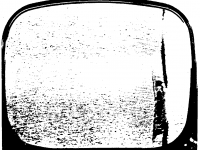
Wow! Figure 13 is a curve to conjure with! Was there a caption to go with the final illustration, and is it mirrored from left to right? I can see hum burs with perhaps RF on them, and also the vertical disturbance which I was expecting to see on the LHS.
Wow! Figure 13 is a curve to conjure with! Was there a caption to go with the final illustration, and is it mirrored from left to right? I can see hum burs with perhaps RF on them, and also the vertical disturbance which I was expecting to see on the LHS.
figure captions
captions for figures:
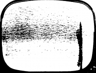
Fig. 11 Typical Examples of Snivet Interference
Fig. 12 Horizontal-Deflection-Tube Plate Characteristic at Zero- Bias Voltage
Fig. 13 Load Line of a 25CD6-G Horizontal-Deflection Tube in a Receiver That Exhibits Strong Snivets
I would guess that figure 13 is for a flyback design so SE.
Have been told by a golfer that a snivet is likely just a small divot!!
captions for figures:
Fig. 11 Typical Examples of Snivet Interference
Fig. 12 Horizontal-Deflection-Tube Plate Characteristic at Zero- Bias Voltage
Fig. 13 Load Line of a 25CD6-G Horizontal-Deflection Tube in a Receiver That Exhibits Strong Snivets
I would guess that figure 13 is for a flyback design so SE.
Have been told by a golfer that a snivet is likely just a small divot!!
house of mirrors
Oh! I see what you mean, Figure 11. I am surprised to see the streak on the right side too, but that was how it was printed in the book. Images are too different examples I think. Here is a re-scan of figure 11 (left side) with more resolution: (really needs grayscale image to do it justice, but too big a file)
Oh! I see what you mean, Figure 11. I am surprised to see the streak on the right side too, but that was how it was printed in the book. Images are too different examples I think. Here is a re-scan of figure 11 (left side) with more resolution: (really needs grayscale image to do it justice, but too big a file)
Attachments
quarks and snivets
Ah! Quarks and Snivets, of course!
A snivet must be a quantized something or other.
Maybe its the smallest possible GREMLIN that can get into electronic equipment. No wonder it was so hard to get rid of them.
Probably cause distortion too. Now, are their left handed and right handed ones, and how do we get rid of them? Probably why someone invented CHARM!
Where are the physicists?
Seriously, quantum mechanics probably are required to explain snivets.
Perhaps Fig. 13 is actually a rare cloud chamber track of a snivet, and its refusal to obey Newton's laws is direct evidence that it is a member of the gremlin group of sub-elementary particles.
Seriously, quantum mechanics probably are required to explain snivets.
Perhaps Fig. 13 is actually a rare cloud chamber track of a snivet, and its refusal to obey Newton's laws is direct evidence that it is a member of the gremlin group of sub-elementary particles.
more snippets on snivets
I found some more info on snivets in the RCA "Electron Tube Design" book, article by M. Bondy titled "Audio Output, Vertical-Deflection, and Horizontal-Deflection Tubes for Receiving Applications" p 669-p681, specifically pp 680,681
"... A disturbance called "snivets" is particularly annoying in the horizontal circuit. Snivets are vertical black bars, lines, or patterns which show up on the right-hand side of a kinescope picture. The effect seems to be caused by an instability in the virtual-cathode region when the anode voltage of the horizontal-deflection output tube is very low (see Fig. 9). It can result in discontinuous jumps in current during the scanning cycle. These current changes are rapid enough to produce a frequency spectrum extending through the very-high-frequency (vhf) band into the ultra-high-frequency (uhf) band. When aperiodic coupling is introduced between the tube and the tuner, the snivet signals are approximately the same in all uhf channels. To avoid this condition, the tube designer must take steps to provide proper suppression at the desired current level. Suitable tube design presents a major paradox to tube engineers. The better the design, that is, the sharper the knee, the higher the plate current at the lowest knee voltage, the more the likelihood that snivets will be present. Conversely, the more rounded the knee and, thus, the less efficient the tube, the less the likelihood of snivets, but these methods usually involve additional parts or reduce output. The design methods, which have been tried with limited success, involve varying the spacing between plate and screen grid by introducing either embosses or a metal part at right angles to the plate structure as shown in Fig. 10. The purpose is to make the plate surface irregular and, in this manner, to improve the stability in the virtual-cathode region. "
This is a little puzzling, since the positive V on G3 fix for snivets squares up the knee. Maybe this fix was found later than 1962 when written or they use more positive V than optimum for square. Seems a little late in the TV game to solve this. I have seen this snivet plate on the inside of a 6KV6 plate. And lots of tubes have an emboss in the plate structure.
Fig. 9 attached. I also tried to find some info on Barkhausen oscillation but so far no luck, I know I've seen this somewhere.
Attachments
Thanks for all the scans, just want you to know this is interesting stuff! ")
I wonder if it isn't forming a tuned circuit, maybe half the plate is resonating or something. Then again that would be tuned, not wideband. For wideband it would have to snap, like a spark, to generate the noise. Hmm any quantum physicists?
Tim
I wonder if it isn't forming a tuned circuit, maybe half the plate is resonating or something. Then again that would be tuned, not wideband. For wideband it would have to snap, like a spark, to generate the noise. Hmm any quantum physicists?
Tim
Transit time
I've had a few thoughts. Line scan is achieved by passing a constant current through an inductor in the anode of the valve, so by the time the right hand side of the scrren corresponds to the largest voltage across the inductor, which is the lowest voltage across the valve, and therefore the knee region of the pentode, as quoted from RCA.
The frequency at which the snivet oscillation happens is probably a transit time effect, not traditional inductors and capacitors. Klystrons and magnetrons are tuned amplifiers where the operating frequency is set by physical dimensions, so distorting the shape of the anode prevents the electrons from all arriving at the same time. When we're in the knee region, the suppressor grid voltage is very similar to the anode voltage, which suggests that there is a change whereby the suppressor grid is not as effective as it should be at suppressing secondary emission at the anode, resulting in electrons flying backwards and forwards between anode and the virtual cathode region near the suppressor grid.
The unstable horizontal position of the visible effects on line scan probably reflects changes in mean energy of electrons in the virtual cathode region around the suppressor grid, which we would normally call noise, perhaps leading to the term "Barkhausen oscillations."
This is all speculation, but it seems to fit the facts so far. Comments/corrections?
Anecdote
From:
http://antiqueradio.org/hallit-67.htm
From:
http://antiqueradio.org/hallit-67.htm
I queried the rec.antiques.radio+phono newsgroup, and soon learned from TV veterans that this is "Barkhausen interference," caused by unwanted oscillation from the horizontal output tube (in this case, a 6BG6GT). The name is used, according to one old manual, because the oscillations are similar to those in a Barkhausen-Kurtz ultra-high frequency oscillator. One characteristic of this interference is that it's more noticeable with weak stations than strong ones. In reading up on the topic, I learned about other, similar types of interference, with amusing names such as "snivets" and "spooks."
Barkhausen-Kurz
a quick google search on Barkhausen found this:
http://www.geocities.com/neveyaakov/electro_science/barkhausen.html
scroll down a ways until the vacuum tube picture shows
its a velocity modulation effect like whats used in microwave tubes
a quick google search on Barkhausen found this:
http://www.geocities.com/neveyaakov/electro_science/barkhausen.html
scroll down a ways until the vacuum tube picture shows
its a velocity modulation effect like whats used in microwave tubes
Barkhauzen-Kurz oscillator
When the plate voltage drops suddenly toward zero, electrons in transit (and there are a bunch in the virtual cathode area) are attracted back to the screen grid and oscillate back and forth thru it. Sort of like a "water hammer" effect in a pipeline when a valve is suddenly closed behind a mass of moving water, pulling a momentary vacuum behind it. Pulling up the suppressor or G3 voltage probably reduces the depth of the virtual cathode so fewer electrons are available to make trouble.
When the plate voltage drops suddenly toward zero, electrons in transit (and there are a bunch in the virtual cathode area) are attracted back to the screen grid and oscillate back and forth thru it. Sort of like a "water hammer" effect in a pipeline when a valve is suddenly closed behind a mass of moving water, pulling a momentary vacuum behind it. Pulling up the suppressor or G3 voltage probably reduces the depth of the virtual cathode so fewer electrons are available to make trouble.
spooks in the electronics
This is from the RCA book again, page741:
"Spook interference is another peculiar effect associated with the horizontal-deflection circuit. This type of interference acquired its name because of its seemly mysterious nature and because its cause eluded explanation for so long. The interference appears as a vertical line or band at the extreme left edge of the raster or, in many cases, may not be visible at all because of overscan of the raster or because it is in the blanked region. Sometimes, spook interference is picked up from a neighboring receiver and may move mysteriously back and forth across the screen: service technicians have referred to this behaviour as "windshield wiper" effect.
Spook interference is generated by the damper tube. The plate current of this tube rises from zero to several hundred milliamperes in a very short time - about 0.1 microsecond. This rapidly increaseing current produces many higher - order harmonics of the horizontal scanning frequency which lie within the television frequency bands. These harmonics often get into the sync circuits and cause picture instability.
It is impossible to eliminate the harmonics produced by the rise of current in the damper tube. However, if chokes are placed in the damper leads at the tube socket, the interference is limited to that radiated by the tube itself. It may also be necessary to put a shield around the damper tube to eliminate radiation from the tube structure."
 Looks like I remembered it on the wrong side of the picture.
the last snivet - I hope!
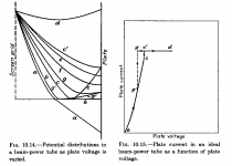
Spangenberg's book "Vacuum Tubes" gives a discussion on pages 260 - 265 of the hysteresis around the knee in plate curves for beam power tubes. The electron distribution changes from one with virtual cathode to one with no virtual cathode in an unstable manner when plate voltage decreases thru the knee. This sudden redistribution of charge most likely triggers the Barkhauzen-Kurz oscillation causing the VHF/UHF frequencies. Figures 10.14 and 10.15 attached.
Spangenberg's book "Vacuum Tubes" gives a discussion on pages 260 - 265 of the hysteresis around the knee in plate curves for beam power tubes. The electron distribution changes from one with virtual cathode to one with no virtual cathode in an unstable manner when plate voltage decreases thru the knee. This sudden redistribution of charge most likely triggers the Barkhauzen-Kurz oscillation causing the VHF/UHF frequencies. Figures 10.14 and 10.15 attached.
Attachments
- Status
- This old topic is closed. If you want to reopen this topic, contact a moderator using the "Report Post" button.
- Home
- Amplifiers
- Tubes / Valves
- 6CM7 another tube in disguise?