Looks OK to me, but I don't take too much notice of square waves.
Square wave test is a good indication to the health of an amplifier. It also shows response peaking which is a pretty good clue to indicate possible instability.
I've come across some shocking test mistakes: Make sure the oscilloscope scope (passive) probes have the trimmer correctly adjusted with a good squarewave before one starts poking with power amps.
richy
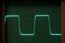
Here's a 10Khz square wave. Is this decent enough?
What I really mean is, is the ringing excessive?
Taking into account the relatively high (26 dB) GNFB the square wave looks quite good. I have seen much worse with some 16 dB GNFB when the OPT is not-so-good.
The OPTs should be at least fairly decent - the Radford transformer design was known for being good. Due to the modern insulation materials, the guy who made them said the inter-winding capacitance would be slightly higher - which may have been what exacerbated the no-load resonance. Hopefully they aren't "worse" as a result of this, just "different"...
Taking into account the relatively high (26 dB) GNFB the square wave looks quite good. I have seen much worse with some 16 dB GNFB when the OPT is not-so-good.
To get a 10Khz square wave like in pic at near full power 100W, one has to work hard at the circuit time constants and that takes into account shoot-through earthing effects of probes. A probe earth in the wrong part of the circuit will cause ringing and will throw one out.
Remember probe inductance "L" = dv/dt. It takes near nothing.
My advice is to stick to 1Khz.The 4 stage amplifier that produced this waveform has 22dB global nfb and the global nfb can be increased another 16dB before instability starts to occur at both bandwidth extremes. This is considered optimum and occurs at optimum transient Q. I can explain the Q bit at another moment.
Remember Fourier analysis. The output transformer for decent quality must have a bandwidth of at least 30Khz (-3dB response) to faithfully reproduce a 10Khz squarewave with minimum ringing. So an expensive transformer claiming -3dB at 75Khz should hold a good squarewave at 25Khz depending on circuit. One pays dearly for this !
richy
Attachments
- Status
- This old topic is closed. If you want to reopen this topic, contact a moderator using the "Report Post" button.
- Home
- Amplifiers
- Tubes / Valves
- HF oscillation with no load, but only on one channel.