Hi there...
I have another question.
If you have a tube amp with no appreciable NFB from the OPT back to driver, so has a fairly high output resistance, would it help to reduce any impedance peaks in the speaker load? As in this:
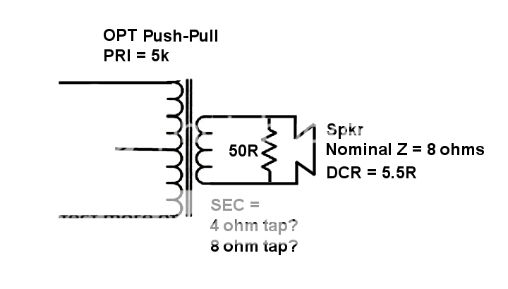
Say this speaker has a ported woofer, and its impedance curve shows a 200 ohm peak at 25Hz and 170 ohm peak at 50Hz. Would it help to strap a 50 ohm resistor across the + and - terminals of this woofer, as in the drawing above?
200 || 50 = 40 ohms
170 || 50 = 38.6 ohms
Substituting a 30 ohm resistor gives this:
200 || 30 = 26 ohms
170 || 30 = 25.5 ohms
The 50 ohm resistor would parallel with the speaker's voice coil DCR of 5.5 ohms to yield 4.95 ohms.
30 ohm resistor paralleled with VC DCR of 5.5 ohms would make 4.65 ohms.
Maybe this parallel resistor idea would work better if the 4 ohm secondary tap from the OPT was used.
So, while this makes sense to me, I know from experience that there's an awful lot I don't know. So I'm asking... What have I overlooked? Any serious downsides to this kind of thing?
Thanks again....
--
I have another question.
If you have a tube amp with no appreciable NFB from the OPT back to driver, so has a fairly high output resistance, would it help to reduce any impedance peaks in the speaker load? As in this:
Say this speaker has a ported woofer, and its impedance curve shows a 200 ohm peak at 25Hz and 170 ohm peak at 50Hz. Would it help to strap a 50 ohm resistor across the + and - terminals of this woofer, as in the drawing above?
200 || 50 = 40 ohms
170 || 50 = 38.6 ohms
Substituting a 30 ohm resistor gives this:
200 || 30 = 26 ohms
170 || 30 = 25.5 ohms
The 50 ohm resistor would parallel with the speaker's voice coil DCR of 5.5 ohms to yield 4.95 ohms.
30 ohm resistor paralleled with VC DCR of 5.5 ohms would make 4.65 ohms.
Maybe this parallel resistor idea would work better if the 4 ohm secondary tap from the OPT was used.
So, while this makes sense to me, I know from experience that there's an awful lot I don't know. So I'm asking... What have I overlooked? Any serious downsides to this kind of thing?
Thanks again....
--
Member
Joined 2009
Paid Member
Hi rongon,
I believe you are thinking in the right direction - it's also my understanding that an amplifier without global feedback will not be able to control the voltage at the speaker as effectively as one with feedback and speaker drivers do not normally have very flat impedance curves. The word impedance is important, its not simply a non-flat resistance, the amplifier current and voltage drawn by the speaker can suffer from relative phase shifts too.
I don't know the answer, it's a complicated topic. I read about speaker manufacturers going to lengths to flatten the impedance. I found a couple of links that may be of interest:
Why and how of serial crossovers
The function of the impedance correction
hope this helps.
- Status
- This old topic is closed. If you want to reopen this topic, contact a moderator using the "Report Post" button.